Products
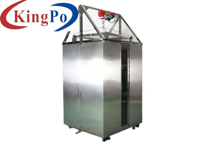
0 To 4℃ Temperature Shock With Splash Water Test Chamber For Automotive Components
Products Description
0 to 4℃ Temperature Shock with Splash Water Test Chamber for Automotive Components
Overview:
This test equipment simulates the load of the component when exposed to splash water as it occurs when driving through puddles. The test serves to verify functioning of the component when subjected to shock-type cooling by means of water. This happens when driving on water roads during the winter. Failure modes are mechanical cracking of the materials or seal failures caused by different temperature expansion coefficients.
Spray the sample heated to the test temperature with a de-ionized water (0-4°C, tap water containing 3% Arizona dust by weight, fine, in accordance with ISO 12103-1. Permanent mixing shall be ensured), at a distance of 300-350 mm from the sample. Each splash duration 3 s, and the water flow is 3-4liters per splash/nozzle. The transition duration <20 s (for manual transition of DUT between temperature storage and splashing) (only required by ISO 16750-4 and GB/T28046.4).
Standards compliant:
Structure:
Chamber type structure, heating and ice water impact are completed in two chambers, with partitions in the middle
Technical parameters:
AC380V single-phase R, N + protection ground;
voltage allowable fluctuation range of 10% V;
Frequency allowable fluctuation range 50±0.5HZ;
TN-S mode power supply or TT mode power supply;
Protective earthing wire grounding resistance is less than 4Ω
The user is required to configure the air or power switch of the corresponding capacity for the equipment at the installation site, and the switch must be independently controlled. When the equipment is used to place the power sample in the box, the sample power supply should use the external power supply, and the power supply of the machine should not be used directly;
Lined up on the left side of the inner chamber, facing the sample
Test sample fixation
Inner chamber material: SUS316# stainless steel 1.2mm thick;
The control box and the test chamber are integral;
The spray water is recovered at the bottom of the test chamber;
The spray nozzle is located on the left side of the test chamber and is fixed by one side;
The bottom of the test chamber is welded into a mesh structure by channel steel, the upper surface is laid with steel plate for mounting the sample mounting frame chassis, and open hole connection blowing heating system on the right side of the test chamber.
Single door
Explosion-proof handle
Fog transparent window
Window wiper
LCD touch screen controller
Divided into heating cycle, spray cycle, pump action, cleaning action, etc.
VW-80000:2009-10 “Electric and Electronic Components in Motor Vehicles up to 3.5t General Requirements, Test Conditions and Tests” clause 9.12 K-12 Temperature Shock With Splash Water
ISO16750-4:2006 “Road vehicles -Environmental conditions and testing for electrical and electronic equipment-Part 4: Climatic loads” clause 5.4.2 Ice water shock test.
GB/T28046.4-2011 “Road vehicles -Environmental conditions and testing for electrical and electronic equipment-Part 4: Climatic loads” clause 5.4.2 Ice water shock test.
Volume, weight and main dimensions
Nominal Internal Volume
800 L
Inner Chamber Effective Size
800×800×1000(mm)
Heating box area
Right side
sample holder size
To be determined
Outer size
1500×1220×1780 (mm) W×D×H
Weight
500kg
Working noise
≤75db, is measured 1 meter away from the machine in front of the machine and 1.2 meters away from the ground
Maximum power
6kw
Maximum current
40A
Power supply
Technical Parameters
Environmental conditions for use
The ambient temperature is +25 ° C, the relative humidity is ≤ 85% R. H, and the value measured under the condition of no sample in the test chamber.
Heating temperature range
Rt 10 °C ~ 120 °C, can be set
Heating rate
RT+10°C ~105°C≤15min
Water flow
3-4 liters per splash / nozzle
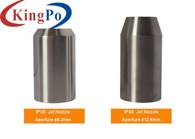
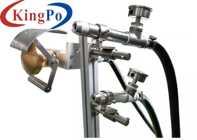
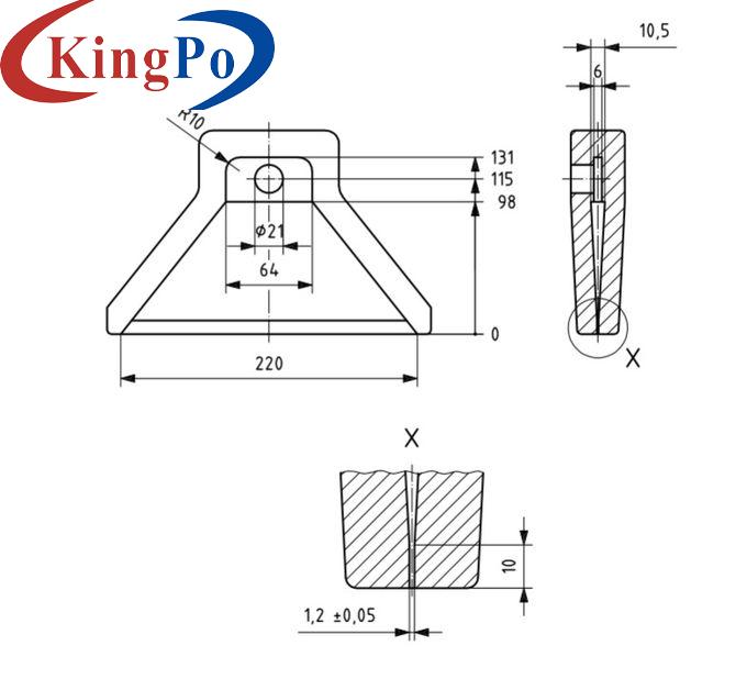
Splash nozzle
2 pcs, Spacing 300mm, made according to following figure

Splash mode
Nozzle spray sample horizontally
Splash water temperature
0-4℃, Refrigeration compressor + mixing water pump
Test medium for splashing
Tap water containing 3% Arizona dust by weight, fine, in accordance with ISO 12103-1. Permanent mixing shall be ensured.
Distance of nozzle to DUT
325±25MM
Number of samples that can be placed
Multiple [the overall size is in the range of W × H × D300 × 400 × 500 (mm)]
Test cycle
Splashing 3s every 30min. Cycle time can be set, as shown in figure 35
Number of cycles
100, can be set
Nozzle arrangement


Fixed on the mounting frame in the chamber
Chamber structure
Outer chamber material: SUS304# stainless steel 1.0mm thick;
Chamber door
Observation window
Located on the door, size 600x600mm
Lighting
Indoor lighting
Control panel
Control man-machine interface, power switch, lighting switch, reserve 7inch man-machine interface
Power distribution control cabinet
Total power circuit breaker, human-machine interface controller, power distribution board, cooling fan, over-temperature protector, water pump.
Water recovery system
Use the bottom recycling cycle to achieve water conservation
Mud water supply system
The SUS316# stainless steel is used to make the mud water supply water tank, and the mud water anti-crystallization stirring device, the mud water supply water pump and the water supply pipe pressure regulating device are ensured to ensure the constant pressure constant current supply spray.
Mud water supplement
Manually, the prepared muddy water can be directly introduced into the mud tank.
Pipe cleaning system
In order to prevent the clogging of the pipeline soil, the water supply will be automatically started after the test, and the soil in the pipeline will be cleaned. The professional clean water supply solenoid valve.
Water supply
Directly connected to the water pipe, the required water supply pressure ≥ 2kgf / cm2
Electrical control system
Controller
Cooling system
Using the France Tecumseh compressor
Communication
Can be used as a monitoring and remote control system to record test data
Operation mode
Program mode / setting mode
Setting mode
Chinese / English interface, touch input
operation control
External operation stop switch signal connector, after turning on the power, simply short the connector to command the controller to execute or stop the action
Safety protection
Spray pump
Overload protection, short circuit protection
Power
Leakage protection, overload and short circuit protection
Stirring motor
Overload protection, short circuit protection
Storage environment requirements
The ambient temperature should be kept within 0 °C ~ +35 °C
Installation site requirements
The left and right side wall panels of the test chamber shall not be less than 800mm from the wall, and the distance from the front wall to the wall shall not be less than 1000mm. Please confirm whether the equipment can enter the doorway or passage, elevator, etc., so as not to affect the progress of your project.
Transport mode
Transportation of the whole machine
