Products
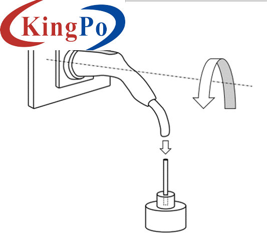
IEC 62196-1 Charging Interface Mechanical Load Test Device Vehicle Connector Testing
Products Description
IEC 62196-1 Charging Interface Mechanical Load Test Device Vehicle Connector Testing
Product Information:
Standard: according to IEC 62196-1:2022.
Samples and restrictions: Charging interface.
Application: The structure of the charging interface should make it easy to insert and remove the charging gun, and should prevent the charging gun from falling out of the socket during normal use. Check whether the maximum force required to pull the charging gun out of the appliance socket is within the range specified by the standard. It is also used to check whether the maximum force required to insert the charging gun into the appliance socket is within the range specified by the standard.
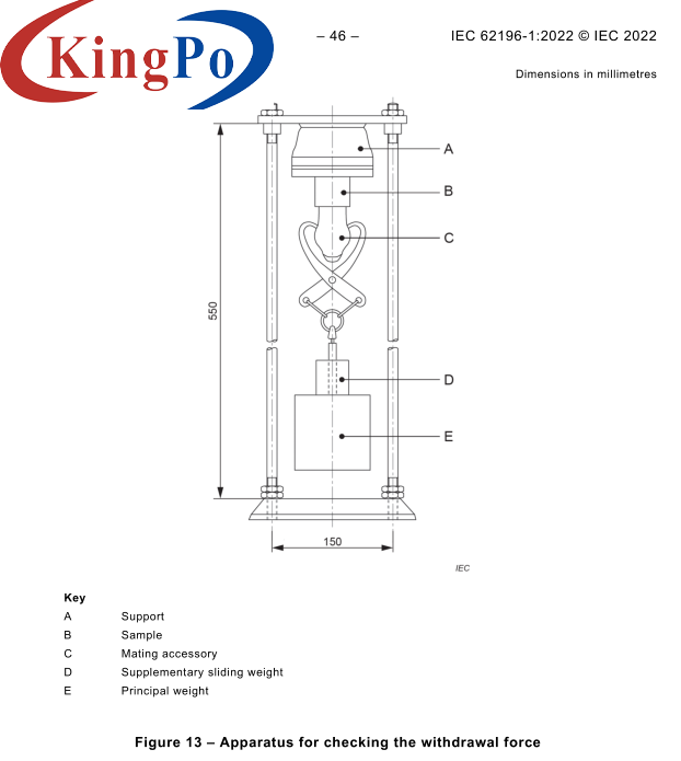
Test principle: Maximum pull-out force of the socket: Apply the maximum pull-out force specified by the standard (the total force of the main weight, additional weight, hook (clamping device), and test plug) to the test plug, and the plug should come out of the socket.
The force for inserting the charging gun into the socket: Place the charging gun vertically downward, place the main weight according to the standard on the charging gun, and then use a 0.8kg weight to freely drop from a height of 5cm to impact the main weight. The charging gun should be inserted into the socket. to the required position of the contact.
Structure and features:
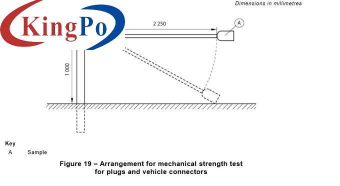
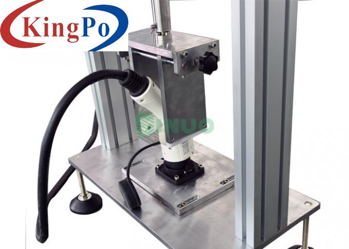
This device consists of the clamping device installed under the top plate A, the main weight F, the additional weight G and the test plug C. The frame of this device is compatible with GB/T20234.1 Figure 5 and GB11918.4 Figure 102, including a horizontal charging interface mechanical load test, locking device test and insertion and withdrawal force test.
Note: The adjustable clamp is used, which can be switched between vertical and horizontal directions, and can clamp all kinds of products; the D clamp is replaced by a hanging ring, which is more convenient to operate; the main weight is directly counterweighted, without the need for a bracket.
Usage environment: Working temperature 5-35℃, humidity 30%-90%.
Technical Specifications:
Made of S136, the pin is the minimum standard size, the tolerance is ±0.01mm, the spacing is ±0.05mm, and the smoothness is 0.8um
Gauge is optional
7.11.8: Charging interface mechanical load test
7.15.1.1: Locking device test
7.17: Plug and pull force test
Test layout drawing
165: 148.5N main weight x1 + 16.5N additional weight x1;
300N: 270N main weight x1 + 30N additional weight x1;
440N: 396N main weight x1 + 44N additional weight x1;
660N: 594N main weight x1 + 66N additional weight x1;
750N: 675N main weight x1 + 75N additional weight x1;
Note: The weight of the main weight includes the weight of the hook, and the weight of the weight is realized by superposition and combination.
Insertion force test layout diagram
Main weight of AC charging gun: 9.2kg
Main weight of DC charging gun: 13.2kg
Additional weight: 0.8kg
Note: The weight of the main weight includes the weight of the clamp and the guide rod. The weight of the weight is achieved through superposition and combination.
AC charging gun: 100N (90N+10N)
DC charging gun: 140N (126N+14N)
1.0kg
Test station
Single station
Gauge configuration
Test items
Main technical parameters of charging interface mechanical load test

Test holding time
60s, the hydraulic cylinder drives the pallet to lift and lower the weight, and the time is manually controlled.
Test frequency
4 times, once in each 90° direction around the horizontal axis, manually
Test load selection

Mechanical load weight configuration
Main technical parameters of locking device test
Test holding time
60s, the hydraulic cylinder drives the pallet to lift and lift the weight, and the time is manually controlled.
Test layout drawing

Main technical parameters of insertion and extraction force test

Insertion force weight configuration
Test
During the test, the locking device needs to be opened
Withdrawal force weight configuration


