Products
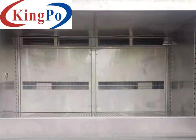
DIN EN ISO 6270-2 Motor Vehicle Components Condensation Test Equipment
Products Description
DIN EN ISO 6270-2 Motor Vehicle Components Condensation Test Equipment
Product overview For Motor Vehicle Components Condensation Test Equipment:
This condensation test chamber meets the condensation test requirements of .VW 80000-2017,DIN EN ISO 6270-2, GS95011-4-2004, DIN 50017, etc.
It simulates the condensation on electronic modules in motor vehicles. It is meant to evaluate the robustness of electronic modules with respect to condensation.
4 movable casters
Using MCGS programmable temperature and humidity controller (7-inch 16-bit true color touch screen); English menu operation mode, 120 groups memory program, each program group contains 1200 program segments, all loops, up to 999 times. Controller: The controller with English display has the function of self-diagnosis, prompts the cause of failure and treatment method, records test data and process, and has a standard RS232 or U disk communication interface.
Technical parameters For Motor Vehicle Components Condensation Test Equipment:
Size
Working area
600*500*830mm(W*D*H)
External size
Approx. 1200*750*1300mm(W*D*H)
Performance
Temperature range
Ambient~60℃ (common used temperature: 38℃/49℃/60℃)
Temperature fluctuation
≤1℃ (≤±0.5℃, tested according to GB/T5170-2008)
Temperature accuracy
0.1 ℃
Temperature deviation
±2℃
Humidity range
100%RH (+0%, -5%, during condensation)
Heating rate
≥10℃/30min (20KG steel with load, meeting the condensation test in VW80000-2013)
Cooling rate
≥65℃/75min (20KG steel with load, meeting the condensation test in VW80000-2013)
Temperature and humidity measuring parts
Use high-precision A-level PT100 temperature sensor for temperature measurement
Heating method
Electric heating, PID adjustment, actuator: solid state relay
Heating system
New-type ceramic heating frame, with heating wire imported from Germany in the middle, thick wire diameter, high temperature resistance, dry burning resistance
Humidification system
External humidification, the humidification tube adopts U-shaped design and over-temperature probe hole,
Dehumidification system
Using evaporator coil dew point temperature laminar flow contact dehumidification method
Water supply system
The humidification water supply adopts automatic control, and the residual water can be recycled, saving water and reducing consumption
Cooling System
Fully enclosed Tecumseh compressor imported from France, using R404 and R23 DuPont environmentally friendly refrigerant
Wind tunnel
Forced circulating air duct to ensure uniform temperature in the working room; heaters, coolers, and temperature sensors are installed in the air duct
Condensate outlet
With outlet holes for studio condensate and unit condensate
Timing range
1~9999 mins/hours
Materials
Outer wall material
A3 iron plate sprayed
Inner wall material
SUS304 Stainless steel plate
Insulation material
Rigid polyurethane foam
Observation window
Three-layer explosion-proof tempered glass window
Lead hole
2 Φ100mm lead holes, with cover and soft plug, located on the left and right walls of the chamber
Sample rack
2PCS, SUS304 stainless steel material, adjustable spacing storage track, sample rack can be adjusted up and down according to needs, evenly bearing 30KG/layer.
Light
There is a lighting lamp on the top of the observation window, which is controlled by the switch outside the door, which is convenient and clear to observation
Movable casters
Humidification tank
High quality 304 stainless steel water tank
Control element
Supply voltage
220v (single-phase three-wire, make a 40a air switch separately, the air switch must have terminals, the power line should be more than 4 square meters; 50hz; power: 4kw
Security system
Studio
Independent studio overheating protector; fan overheating protection
Cooling System
Compressor overpressure; Compressor overcurrent; Compressor overheat; Discharge temperature protection
Power Systems
Power supply phase loss and phase sequence error protection; Leakage protection; Heater over-temperature protection; Heater short-circuit and other over-current protection
Other
Test box shell grounding protection
Installation environment
The location of the equipment should be reserved for the floor drain or the drain pipe interface. The drain pipe should be divided into 4 pipes, and the mouth of the drain pipe should be flat with the ground.
Temperature: 20℃~28℃, relative humidity: ≤85%, air pressure: 86kpa~106kpa
The installation site should be flat and well ventilated. There is no strong vibration around the equipment, and there is no strong electromagnetic field around the equipment
There are no flammable, explosive, corrosive substances and dust around the equipment. Appropriate use and maintenance space is left around the equipment


