Products
IEC 60068-2-75 EVSE Test Equipment IK Pendulum And Vertical Impact Test Device
Products Description
IEC 60068-2-75 EVSE Test Equipment IK Pendulum And Vertical Impact Test Device
Product Information For IK Pendulum And Vertical Impact Test Device:
Standard: IEC60068-2-75:1997” Environment testing for electric and electronic products Part2: Test methods Test Eh: Hammer tests IDT”
IEC62262:2002 "Degrees of protection provided by enclosures for electrical equipment against external mechanical impacts (IK code)"
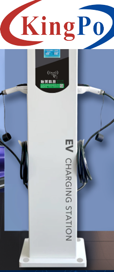
Sample: Electric vehicle charging pile
Test purpose: It is used for the mechanical strength test of electric vehicle charging piles used for charging vehicles, and is also used for the mechanical strength verification of metal sheets such as transformer cabinets and non-metallic electric energy metering cabinets
Test principle: According to the test Eha: pendulum, the impact element is freely released at a certain height through a 1-meter pendulum tube, and hits the sample at the lowest point in the vertical direction, and through the conversion of gravitational potential energy to kinetic energy, the purpose of impact testing on the sample is achieved.
According to the test Ehc: vertical drop hammer, the impact element is released freely at a certain height, falls vertically in a static state, hits the sample, and through the conversion of gravitational potential energy to kinetic energy, the purpose of impact testing on the sample is achieved.
Structure For IK Pendulum And Vertical Impact Test Device:
1. The trolley structure is adopted, the mounting bracket seat can be adjusted up and down, and the impact angle can be adjusted to match the height requirements of charging piles of different sizes and different impact points of charging piles
2. The motor is used to drive the lifting, which is easy to operate
3. Both pendulum and vertical impact are released by electromagnet
4. The pendulum has the function of anti-secondary impact
Technical Parameters For IK Pendulum And Vertical Impact Test Device:
W (0.2~1m) *D (0.2~1m) *H (0.5~1.5m)
1. Pendulum impact
2. Vertical impact
1. Impact component equivalent mass 5Kg±1%
2. A steel pipe with a pendulum length of 1000 mm, an outer diameter of 15.9 mm, and a wall thickness of 1.5 mm
3. Swing vertical height (drop height): 0-500mm, scale display
4. The position of the impact point of the pendulum: adjustable up and down by electric motor, stroke 300-1500mm
5. Fixation and release of the impact element: fixation and release of the plug-in electromagnet
6. Anti-secondary impact function: brake disc brake
1. Impact component equivalent mass 5Kg±1%
2. One piece of conduit with a flange mounting plate
3. Vertical drop height: 500mm, the conduit is fixed, and the distance from the bottom of the impacting element to the bottom of the conduit
4. Vertical impact point position: Electric up and down adjustable, stroke 300-1500mm, horizontal mechanically adjustable, can extend the equipment 800mm
5. Fixation and release of the impact element: Suction cup electromagnet fixation and release
Attached: Table 1 Impact component characteristics
≤1
±10%
2
±5%
5
±5%
10
±5%
20
±5%
50
±5%
Table 2 Drop height
Table 3 Correspondence between IK codes and their corresponding collision energies
Control and operation mode
Electrically integrated control, anj operation, with remote control operation, electromagnet release
Test sample range

Impact method
Impact energy
20J (2,5,10,50J energy can be customized)
Main parameters of pendulum impact
Main parameters of vertical impact
Bottom plate and frame
Thickened load-bearing steel base plate, four industrial aluminum profile column frames
Way of moving
With support and roller feet, it can be moved to the position of the impact point of the sample
Attached schedule
References for impact energy and impact element selection
Energy/J
Equivalent mass ± 2% kg
0.25(0.2)
0.5
1.7
5
5
10
Material
Nylon
Steel
R/mm
10
25
25
50
50
50
D/mm
18.5(20)
35
60
80
100
125
f/mm
6.2(10)
7
10
20
20
25
r/mm
-
-
6
-
10
17
l/mm
Determined based on equivalent mass adjustment, see Appendix A
Energy/J
0.14
0.2
(0.3)
0.35
(0.4)
0.5
0.7
1
2
5
10
20
50
Equivalent mass/kg
0.25
(0.2)
0.25
(0.2)
0.25
(0.2)
(0.2)
0.25
0.25
0.25
0.5
1.7
5
5
10
Drop height ±1%mm
56
(100)
80
(150)
140
(200)
(250)
200
280
400
400
300
200
400
500
Note 1. See Note 3.2.2; Note 2. The energy unit joule (J) in this part is derived from the standard gravitational acceleration (g), and the value of g is rounded to 10m/s².
IK code
IK00
IK01
IK02
IK03
IK04
IK05
IK06
IK07
IK08
IK09
IK10
Collision energy/J
a
0.14
0.2
0.35
0.5
0.7
1
2
5
10
20
Note 1. If a higher collision energy is required, the recommended value is 50J; Note 2. Some national standards use one digit to represent the specified collision energy. In order to avoid confusion with it, the characteristic number is represented by two digits.
Unprotected according to this standard


