Products
IEC60884-1 20N Gauge For Checking Non Accessibility Of Live Parts Through Shutter
Products Description
IEC60884-1 20N Gauge For Checking Non-Accessibility Of Live Parts Through Shutter
Product information:
This gauge conforms to the standard requirements of IEC60884-1 clause 21 figure 9 and figure 10, IEC 62196-1:2020 clause 10.2, and etc. The SN2110 test probe with 20N force is used to test whether the live parts inside can be touched.
Technical parameters:
Test procedures and operation:
Please refer to the relevant standards.
Take IEC 62196-1:2020 clause 10.2 as an example:
For accessories provided with shutters, the shutters shall be constructed that live parts are not accessible without a plug-in engagement, with the gauges shown in Figures 9 and 10.
The gauge according to Figure 9 is applied to the entry holes corresponding to the live contacts and to any other opening of the engagement surface with a force of 20 N.
The gauge is applied to the shutters in the most unfavourable position, successively in three directions, to the same place for approximately 5 s in each of the three directions.
During each application the gauge shall not be rotated, and it shall be applied in such a way that the 20 N force is maintained. When moving the gauge from one direction to the next, no force is applied but the gauge shall not be withdrawn.
To calibrate the gauge, a push force of 20 N is applied on the steel rigid wire in the direction of its axis: the characteristics of the gauge internal spring shall be such that the surface A-A' is brought practically to the same level as the surface B-B' when this force is applied.
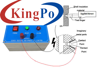
The gauge “A” is equipped with a connection cable, for verifying whether the LIVE PARTS touched, recommended to work with our anti-shock probe experiment device or a 40~50V voltage indicator. Connect the connection cable of the probe with one terminal of the anti-shock probe experiment device, and then use an additional cable to wire the LIVE PART of specimen with the other terminal of the anti-shock probe experiment device. Showing as following reference picture:
Notice:
1. Please do not damage the appliance shape (such as scratching, bending, etc.).
2. Prevented from dust and moisture environment, in order to avoid the oxidation to affect the dimensional accuracy.
3. Be careful of electric shock.
Bar width (mm)
3+0.03 0
Bar thickness (mm)
1+0.015 0
Bar length(mm)
80±0.5
Chamfer edge(mm)
R0.2±0.05
Bar material
Rigid steel
Guard diameter (mm)
φ50
Guard thickness (mm)
5
Guard material
Nylon
Handle diameter (mm)
φ30
Handle length (mm)
85
Handle material
Nylon
Built-in force (N)
20


