Products
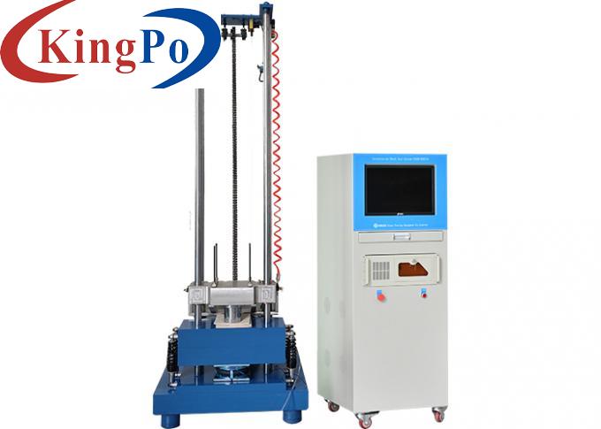
IEC 60335-2 Acceleration Shock Test System For Impact Resistant Test Electronic Product
Products Description
IEC 60335-2 Acceleration Shock Test System For Impact Resistant Test Electronic Product
Product Information For Acceleration Shock Test System:
It is required by IEC 62133-2:2017 clause 7.3.8.2, IEC 60335-2-25 Annex BB, YD/T 2344.1 and etc.
This machine is mainly suitable for the impact resistant test of electronic products, aerospace, ships, military, automobile parts, transportation and other fields. By selecting different waveform generators, impact tests of half sine wave, back peak sawtooth wave or square wave can be carried out.
It meets MIL-STD-202F, IEC-68-2-27, MIL-STD-810F, MIL-STD-883E and etc.
Technical Parameters For Acceleration Shock Test System:
Device Performance For Acceleration Shock Test System:
1. Working platform: high strength imported aluminum alloy working platform.
2. Lifting mechanism: motor drives ball screw to lift the working platform.
3. Lifting height control: the lifting height is measured by the photoelectric encoder component installed on the base. The photoelectric encoder has high precision, strong anti-interference ability and high reliability to ensure the impact repeatability.
4. Brake system: using pneumatic brake and strong friction brake to prevent secondary impact braking function, to prevent secondary rebound
5. Buffer system: effectively reduce the impact of impact test on the ground, a self-buffer system is designed, which is composed of base, damper and air bag.
Half sine wave generator is mainly made of engineering rubber or wool felt. It consists of a variety of different thicknesses connected in series, forming a variety of stiffness, to achieve different impact pulse width.
Emergency stop switch: It can cut off the circuit under emergency circumstances by forcibly disconnecting the contact welding of the action mechanism.
The system conforms to MIL-STD-810 and IEC68-2-27 standards. It has accurate and fast impact waveform capture capability, with the highest sampling rate up to 1MHz. You do not need to worry about even narrow impact events being missed.
It is also an integrated solution, you don't have to much busy to view and record, it can capture the impact event to generate a report shall be complete, more importantly, it also provides the function of shock response spectrum (SRS), can help you for shock pulse potential damage for effective evaluation of actual system. Finally, auxiliary analysis of force deformation, impact response and so on can help you understand the impact results in more detail.
Use Environment For Acceleration Shock Test System:
1. Site temperature: 5℃~+28℃ (average temperature within 24 hours ≤28℃);
2. Relative humidity: ≤85%RH;
3. Air source: 0.5-- 0.8MPa
4. Power supply conditions: single-phase three-line;
5. Voltage input: AC220V;
6. Allowable frequency fluctuation range :(50±0.5) Hz;
7. The grounding resistance of the PGND cable is less than 4 Ω.
8. Please configure an air or power switch of corresponding capacity (100A) for the device at the installation site, and this switch is used independently for the device.
Working platform
200 × 250 mm
Working platform Material
High-strength imported high-quality aluminum alloy
Maximum load
10kg
Peak acceleration
20—2000 G
Pulse duration
0.2—18ms
Equipment size
660 × 700 × 2380mm
Equipment weight
820 kg
Measuring System
Input channel
2 channels
Sampling frequency
192KHz
Input form
Voltage, Electric Charge
Voltage range
-10v--+10v
Coupling method
AC, DC, ICP
Shock waveform
Half Sine
Communication interface
USB2.0
Support standard
National standard, national military standard, U.S. military standard, user-defined standard
Operating system
Microsoft Windows7/10
System Acceleration Sensor
Brand
YMC
Output method
Charge type
Sensitivity
3.93pC/g
Frequency range
0.5—12KHz
Acceleration range
±2500G
Working environment
-40~+160℃
Other Instructions
Power supply
Single phase 220V±10%
Compressed air
0.5—0.8Mpa
Temperature
RT~40℃
Humidity
25℃<85RH%


