Products
IEC 60086-4 Battery Test Equipment Mechanical Abuse Of Cylindrical Cells Impact Test
Products Description
IEC 60086-4 Battery Test Equipment Mechanical Abuse Of Cylindrical Cells Impact Test
Overview:
Impact Mass
9.1kg
Impact Height
0~880mm
Control Method
PLC Touch Screen Control+ Remote Control
Crossing Bar Diameter
15.8 mm (Place on central position in cross direction and the heavy bar and steel bar is parallel to battery bottom)
Test Room
W300 X D300 X H300mm
Internal Material
SUS 304# Stainless steel(thickness 1.0mm compensation and external chamber thickness 80mm)
External Material
Cool-Rolled Plate (thickness 1.0mm)
Air Vent
150mm, on the top of back of chamber
Chamber Gate
Single Door, Viewing Window, cold-rolled door lock
Viewing Window Size
390 X 360mm (20mm Dual layer glass explosion proof film)
Elevating Method
Motorized
Top/bottom impact surface
Steel Plate
Chamber Size
W940 X D780 X H1620mm
Power Source
AC 220V, 60Hz
Power
2.0KW
Gross Weight
About 250KG
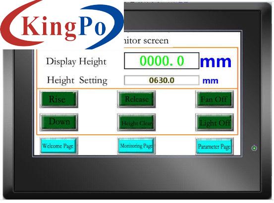
Touch Screen Monitoring
Battery impact test equipment is used to test the safety performance of batteries from different heights through different masses and different impact areas. Batteries are qualified if there is no flame or explosion after the impact test.
Standards Compliant:
Comply with IEC 60086-4: 2014 Article 6.5.2 Figure 3, UL1642:2012 Article 14 Figure 14.1, UL 2054, UN38.3, GB/T 18287-2013, GB 31241-2014, GB-31241-2014, QB/T2502 and other standards.
Technical Parameters:
(The mass can be raised to a height and released to ensure the mass dropping free without inclining and swing)

Test Procedure:
The impact test is applicable to cylindrical cells with a diameter greater than 20 mm.
The test cell or component cell is placed on a flat, smooth surface. A stainless steel bar (Type 316 or equivalent) 15.8 mm ± 0.1 mm in diameter and at least 60 mm in length or the longest dimension of the cell, whichever is greater, is placed across the centre of the test specimen. Using a nearly frictionless vertical sliding rail or hammock, a weight of 9.1 kg ± 0.1 kg is dropped from a height of 61 cm ± 2.5 cm onto the intersection of the bar and the test specimen in a controlled manner, with minimum resistance to the falling weight. The vertical rail or hanger used to guide the falling weight shall be at an angle of 90 degrees to the horizontal support surface.
The longitudinal axis of the test specimen at impact shall be parallel to the plane and perpendicular to the long axis of the stainless steel bar across the centre of the test specimen (see Figure 3).


