Products
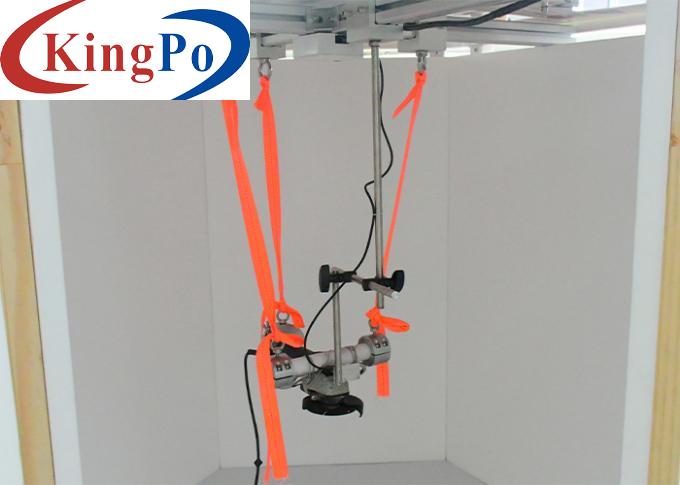
IEC 60745-2-3 Angle Grinder Guard Strength Test Equipment For Test Mechanical Strength
Products Description
IEC 60745-2-3 Angle Grinder Guard Strength Test Equipment For Test Mechanical Strength
Product Information:
This device adopts a hexagonal test box according to the relevant standard requirements of IEC60745-2-3 clause 20.101.3.
Angle grinder guard strength test equipment is used to assess the mechanical strength and integrity of the guards on angle grinders. The purpose of this equipment is to ensure that the guards effectively protect users from potential hazards and remain securely attached during operation. Here are some key features and components typically found in angle grinder guard strength test equipment:
Test Fixture: The equipment includes a test fixture or holder that securely holds the angle grinder during the testing process. This fixture is designed to accommodate various sizes and types of angle grinders and allows for consistent positioning of the guard during testing.
Force Application Mechanism: The test equipment incorporates a force application mechanism that enables controlled and adjustable forces to be applied to the guard. This mechanism can involve hydraulic, pneumatic, or mechanical components, depending on the specific design of the testing equipment.
Force Measurement System: To measure the forces applied to the guard accurately, the testing equipment is equipped with a force measurement system. This system typically includes load cells or force transducers that convert the applied force into electrical signals for measurement and analysis.
Adjustable Fixing Mechanism: The equipment features an adjustable fixing mechanism that simulates the attachment of the guard to the angle grinder. This mechanism allows for the proper positioning and secure fixing of the guard during the strength testing.
Force Display and Control: The testing equipment is equipped with a force display unit that shows the measured force applied to the guard during testing. It also allows operators to control and adjust the applied force within the desired range. This ensures consistent testing conditions and facilitates accurate evaluation of guard strength.
Safety Features: Safety considerations are vital in the design of angle grinder guard strength test equipment to protect operators and prevent accidents during testing. This may include safety enclosures, protective shields, and safety protocols to ensure safe handling of the angle grinder and guard during testing.
Test Procedure: The equipment may include a standardized test procedure that outlines the specific steps and parameters for conducting the guard strength test. This procedure ensures consistent and repeatable testing across different angle grinder models and guard designs.
Data Logging and Analysis: Some guard strength test equipment may have data logging capabilities to record and store test data, including applied forces and test results. This data can be analyzed to assess the strength and integrity of the guards, evaluate their performance under simulated conditions, and ensure compliance with industry standards and regulations.
Angle grinder guard strength test equipment is crucial for manufacturers, regulatory bodies, and quality control departments to ensure the safety and reliability of angle grinders. By subjecting the guards to controlled forces, this equipment helps identify potential weaknesses or failure points, allowing manufacturers to make necessary improvements and ensure that the guards effectively protect users from potential hazards during angle grinder operation.
Main technical parameters:
Working power supply: AC/DC85~260V
Measuring cycle: 1 second
Measuring frequency: HB966N: 1~15KHz
Displayed value: input value × magnification A ÷ magnification B
Magnification A: -199999~999999
Magnification B: 1~999999
Measuring range: -199999~999999
Contact capacity: AC250V/3A
Contact life: 105 times
Transmission output: 0~20mA, 4~20mA
Transmitting load: not less than 500Ω, photoelectric isolation
Communication output: RS485 (photoelectric isolation) MODBUS_RTU protocol
Dimensions: 96×48×82mm (horizontal)
Hole size: 92+1×44.5+1mm
Working environment: 0~50℃
Function description:
1 The outermost layer is made of solid wood, and each piece is connected by a hinge, which can be disassembled. One of them uses a living hinge, which can be easily opened, so that the operator can enter the inside of the box to install the test sample.
2 The second layer is spliced with 30mm thick pine boards, which can be disassembled.
3 The third layer is made of high-density foam board, which is raised around the box body.
4 The top of the box is protected with plexiglass.
5 Non-contact high-precision photoelectric sensors are used for monitoring the speed of the grinding disc, and the speed is observed with the display instrument. The sensor is installed inside the hollow steel pipe. The speed value when the angle grinding disc is broken can be monitored.


