Products
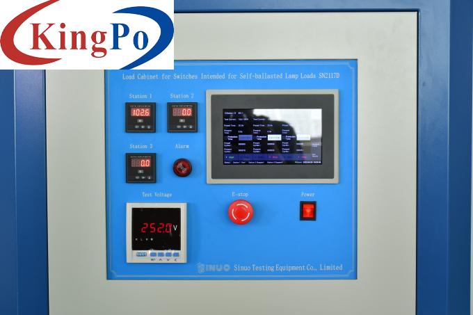
Touch Screen Switch Load Cabinet For Self Ballasted Lamp Loads IEC60669-1
Products Description
Self-Ballasted Lamp Switch Load Cabinet For Self Ballasted Lamp Loads IEC60669-1
Each set of equipment provides a closing control device (select the “calibration” function on the touch screen), and each time it is conducted at a 90-degree angle, this function can be used for initial adjustment and calibration verification of the equipment.
Power supply: AC220±5%/50Hz,10KVA
The load cabinet uses an integral steel structure frame and a Toyota white seal plate. The control panel is in the upper part of the equipment, there are external power switch, voltmeter and power display instrument, alarm and touch screen, resistor and capacitor load combinations, AC contactors and relays. There are terminals in the lower part of the load cabinet, which is connected with the specimen through the cables to output current and voltage during the detection process.
Standards For Self-Ballasted Lamp Switch Load Cabinet:
IEC60669-1:2007 "Switches for household and similar fixed-electrical installations - Part1:General requirements" clause 19.3
Test Principle For Self-Ballasted Lamp Switch Load Cabinet:
Switches intended for self ballasted lamp (SBL) loads shall withstand, without excessive wear of other harmful effect, the electrical and thermal stresses occurring when controlling self ballasted lamp circuits.
The purpose is to check whether the switch has continuous flashover, whether the contacts are welded, closed or disconnected for a long time, excessively worn or otherwise.
Technical parameters For Self-Ballasted Lamp Switch Load Cabinet:
Test Channels
1 or 2 or 3 channels can be customized, independently output
Electrical Control Method
Touch screen + button control, digital display
Voltage Display Value
0~300V, accuracy level 0.5
Power Display Value
0~9KW,accuracy level 0.5
Output Voltage
0-280V adjustable, ensure test voltage to be 250V~
Preset Rated Voltage of Switch
Each channel 250V~, rated current 10A,13A,16A,20A are optional
Working Parameter Setting
All parameters are set according to 250V~, including W, I peak, I2t and surge current waveforms.
Calibration Function
(The calibration method is to extract the current waveform from an external oscilloscope, and then use the calculation method to obtain the I2t value, the oscilloscope is provided by client)
Protective Function
Long time breaking / long time conduction protection, protection time: 1 ~ 99S can be preset, the equipment will be stopped and alarm will be given out when protection occurs.
Use Environment
Place of use: Atmospheric pressure 80~106kpa;
Environment temperature:5~40°C;humidity(20~80)%RH;
No violent shaking, vibration, no electromagnetic interference, no dust, no explosive and corrosive gases, good heat dissipation
Main features:
1. The load conditions required by the standard has been preset before factory. As long as the test voltage is adjusted to 250V~, operator presses switch button corresponding to the rated current of the switch to be tested, then the rated power, shock waveform, Ipeak and I2t meet the corresponding requirements of the standard.
2.The input voltage and output power can be digital displayed, the surge current can be observed on the pointer current meter.
3. There are 3 working stations, 3 switches can be tested at the same time.
4. With calibration mode and calibration dedicated port, built-in 90-degree closing plate, easy for measuring output waveform, Ipeak current value and I2t energy value, thus, fully meets the standard requirements of calibration.
5. The device is equipped with a voltage regulator, which can achieve the voltage of 250V~ required by the switch test without external voltage regulator.
Dimensions of the equipment: approx.: 800 × 800 × 1800 (mm) W × D × H, weight: 200kg


