Products
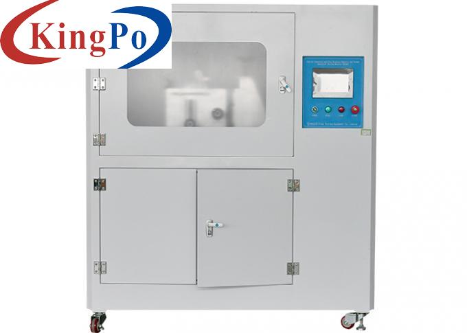
Switched Socket Outlets Vehicle Connectors Withdrawal Force Test Apparatus
Products Description
IEC 62196-1 Switched Socket-outlets Vehicle Connectors Withdrawal Force Test Apparatus
Product information:
This withdrawal force test equipment conforms to IEC 62196-1Ed.4CDV 2020 clause 14.1.5, 14.1.6, fig13, fig14, table 5.It is used to check the maximum force required when the plug is pulled out of the socket-outlet or connector.
Technical parameters:
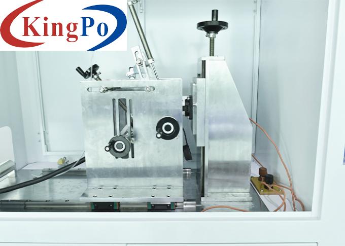
1. The frame is composed of a bottom plate, a column, a sample installation fixture, and a weight lifting mechanism, made of stainless steel. Please refer to figure 13 of IEC 62196 2020.
2. The maximum withdrawal force / lateral stress combination and weight combination are as follows:
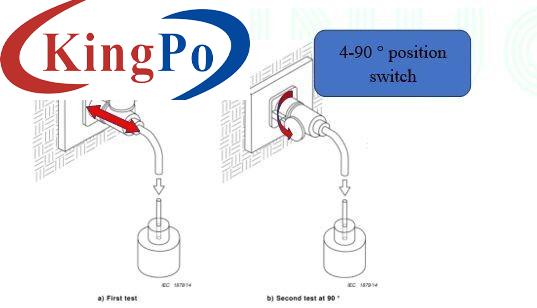
Adjust the device to the horizontal clamping state by the horizontal and vertical switching mechanism, and switch the force direction of the clamp by the 4-90 ° rotating mechanism. Please refer to figure 14 of IEC 62196 2020.
4. The test plugs can be customized according to client's requirements.
Test Procedures (Excerpt from IEC 62196 2020 clause 14.1.5 and 14.1.6):
1. Checking the withdrawal force:
Test plug is inserted into and withdrawn from the socket-outlet or vehicle connector ten times. It is then inserted again with a mass being attached to it by means of a suitable clamp.
The total mass of the plug, the clamp, the carrier, the principal and the supplementary weight shall exert a pull force according to Table 5. The supplementary weight shall be such that it exerts a force equal to one-tenth of the withdrawal force. The retaining means, if any, shall be opened.
The principal weight is hung without jolting on the test plug, and the supplementary weight is allowed to fall from a height of 5 cm onto the principal weight.
After this test, the total weight shall be maintained for 60 s.
2. Verification of the latching device
The test plug is inserted into and withdrawn from the socket-outlet or vehicle connector ten times. It is then inserted again with a mass being attached to it by means of a suitable clamp.
The total mass of the plug, the clamp, the carrier, the principal and the supplementary weight shall exert a pull force according to Table 5. The supplementary weight shall be such that it exerts a force equal to one-tenth of the withdrawal force. The retaining means, if any, shall be opened.
The principal weight is hung without jolting on the test plug, and the supplementary weight is allowed to fall from a height of 5 cm onto the principal weight.
After this test, the total weight shall be maintained for 60 s.
The test of 14.1.6 is repeated three times, rotating the socket-outlet of 90° on the vertical plane each time (see Figure 14 b)
Sample type (AC A)
Withdrawal N
Principal weight N
Supplementary weight N
6-40
165
148.5
16.5
41-80
300
270
30
81-150
440
396
44
151-250
660
396+148.5+49.5
66
DC Rated current
Any
750
396+148.5+49.5+15
75
Note: The principal weight already contains the test plug and hook weight

