Products

Ringing Wave Signal Test Generator IEC 61000-4-12 EMC Test Equipment
Products Description
IEC 61000-4-12 Ringing Wave Signal Test Generator
Product overview:
The ringing signal generator is used to simulate non-repetitive damped oscillatory transient waves in low voltage power lines, control lines and signal lines in both public and private networks. Provides an ideal, normative basis for assessing the immunity of electrical and electronic equipment for domestic, commercial and industrial use.
Transients due to power and control switching (or triggered by lightning strikes), generate ringing wave interference on power lines, control lines and signal lines. To establish a common criterion for the evaluation of the immunity performance of electrical and electronic equipment for domestic, commercial and industrial use.
This ringing signal generator conforms to standards of IEC 61000-4-12/ GB/T 17626.12 “Electromagnetic compatibility (EMC)– Testing and measurement techniques –Oscillatory Waves Immunity test” & ANSI-C62-41 “IEEE Guide for Surge Voltages in Low-Voltage Ac Power Circuits”, it required by IEC 61009-1 clause 9.19.1, etc.
Technical parameters:
Open Circuit Voltage Decay Rate
Structure:
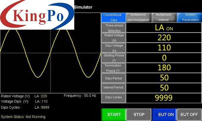
7-inch touch LCD interface, rich in functions, easy for operation and upgrading software
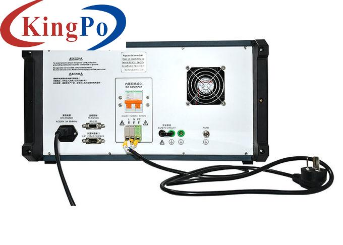
Built-in single-phase 10A (16A) power network, 2-in-1, miniaturized design.
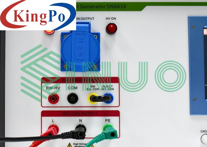
EUT output comes with high-strength panel socket, and the test sample connection is more convenient and reliable.
Built-in EUT operating voltage, current monitoring, overvoltage, overcurrent protections
Intelligent program-controlled high-voltage power supply, with built-in high voltage overvoltage, overcurrent and short circuit protections.
Ringing wave output intelligent detection, with warnings for voltage error and no output
Self-diagnosis function, can intelligently judge the abnormal outputs of high voltage and ringing wave.
The main switch adopts the imported switch to ensure stable waveform, with strong comparability and long life.
The waveform will be shown by an external oscilloscope (oscilloscope should be prepared by user)
Open Circuit Voltage Oscillation Frequency (1/T)
100kHz±10%
Open Circuit Output Voltage (PK1)
(250V~4000V)±10%
Open Circuit Voltage Waveform Front (T1)(10%~90%)
PK1:0.5μs±30%
40%<(PK2)/(PK1)<110%
40%<(PK3)/(PK2)<80%
40%<(PK4)/(PK3)<80%
Short Circuit Current Wave Front (T2) (10%~90%)
P1 ≤0.9μs
Short Circuit Current (PK1) at 3500V
292A ± 10% at 12Ω
Short Circuit Current (PK1) at 3500V
117A ± 10% at 30Ω
Adjacent Pulse Interval
1s~99s
Number of Pulses
1~9999 times
Output Method
Automatic positive and negative polarity switching or alternation
Output Impedance
12Ω, 30Ω
Phase Injection Method
Asynchronous or synchronous (0°~360°)
Sample Coupling / Decoupling Network
Optional, coupling / decoupling network with lightning surge generator


