Products
CISPR 15 Radiation Emission RE Electromagnetic Compatibility 30MHz-6GHz Test System
Products Description
CISPR 15 Radiation Emission RE Electromagnetic Compatibility EMI Test Systems
Standards & Clauses:
CISPR 11 / GB4824: Industrial, scientific and medical (ISM) radio-frequency equipment and similar equipment –Radio-frequency disturbance characteristics –Limits and methods of measurement
Samples and Restrictions:
Engineering medical (ISM) equipment and information technology (ITE) equipment
Application:
Used to test EUT radiation emissions.
Test Principle:
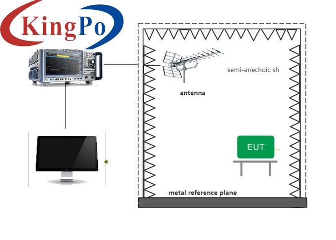
CISPR 11, CISPR 32 and other standards, engineering medical (ISM) equipment and information technology (ITE) equipment, the need to open the premises or anechoic chamber 30MHz above the emission test.
Structure:
Main test equipment: receiver, EMI receiving antenna, preamplifier, EMC test software.
Use Environment:
Power supply: 380V ± 10% 50 / 60Hz
Technical Parameters:
CISPR 12: Vehicles, boats and internal combustion engines—Radio disturbance characteristics—Limits and methods of measurement for the protection of off board receivers
CISPR 13 / GB13837: Sound and television broadcast receivers and associated equipment –Radio disturbance characteristics –Limits and methods of measurement
CISPR 14-1 / GB4343.1: Electromagnetic compatibility. Requirements for household appliances, electric tools and similar apparatus -Part 1: Emission
CISPR 15 / GB17743: Limits and methods of measurement of radio disturbance characteristics of electrical lighting and similar equipment
CISPR 22 / GB9254: Information technology equipment – Radio disturbance characteristics –Limits and methods of measurement
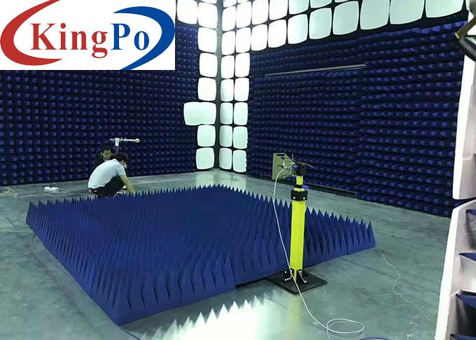
Test environment: anechoic chamber (not included in this system, optional, or customer should prepare it)
Ambient temperature: 5 °C ~ +40 °C, there should be no high concentration of dust, corrosive gas, flammable and explosive objects
Main Test Equipment
Receiver, EMI receiving antenna, preamplifier, EMC test software.
Test Environment
Anechoic chamber
Measuring Distance
It refers to the distance between the point where the EUT is closest to the antenna and the projection of the center of the antenna on the ground. Priority is given to the 10 m method, optional 3 m method
Antenna Height
The height of the antenna from the ground should be varied within the specified range to obtain the maximum reading that would occur when the direct and reflected waves are in phase. For measuring distances ≤ 10 m, the height of the antenna is preferably varied from 1 m to 4 m.
Frequency Range
30MHz-6GHz
Schematic Diagram

