Products
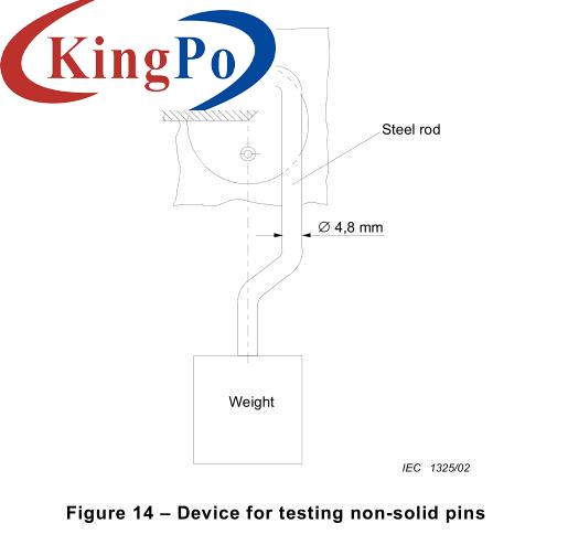
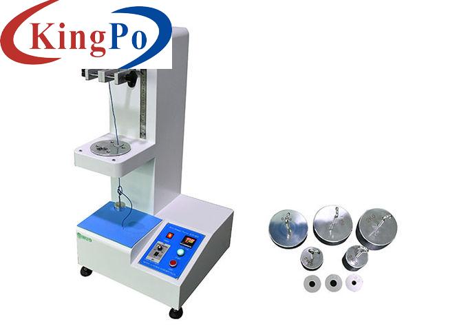
IEC 60320-1 Figure 2 Device For Checking Non-Solid Pins For Plug pins Testing VDE Type
Products Description
IEC 60320-1 Figure 2 Device For Checking Non-Solid Pins For Plug Pins Testing VDE Type
Product information:
The appliance is checked by the test of IEC60884-1:2022 clause 14.2, figure 17, for pins which are not solid, by the following test which is made after the test of clause 21. A force of 100 N is exerted on the pin, which is supported as shown in IEC60884-1, IEC60884-1, figure 14, for 1 min in a direction perpendicular to the axis of the pin, by means of a steel rod having a diameter of 4,8 mm, the axis of which is also perpendicular to the axis of the pin. During the application of the force, the reduction of the dimension of the pin at the point where the force is applied shall not exceed 0,15 mm. After removal of the rod, the dimensions of the pin shall not have changed by more than 0,06 mm in any direction.
Features:
When it comes to checking non-solid pins, such as hollow or tubular pins, a specialized device known as a pin gauge or pin micrometer can be used. A pin gauge is a precision measuring instrument designed to verify the diameter and dimensional accuracy of non-solid pins. Here's an overview of how a pin gauge works and its key features:
Design and Construction: A pin gauge consists of a set of cylindrical pins, each with a specific diameter. These pins are typically made of hardened steel and are arranged in a stepped or progressive order. The pins are securely held in a handle or holder, which provides stability during the measurement process.
Technical parameters:
Operation Steps:
1. Before using it for the first time, the operator needs to be familiar with the relevant standards in order to use the test device more effectively and correctly and complete the test.
2. Put the plug and pin on the bracket according to the standard requirements, and then use the handle to lifting the weight. At this time, apply a pressure of 100N to the plug. After 1 minute, lower the lifting device and release the weight pressure. The direction of force is against the central axis of the pin, and the force is applied to the central axis of the pin through a steel rod of Φ4.8mm.
3. During the force application, the size of the position where the pin is stressed may be reduced, but the reduction value cannot exceed 0.15mm.
4. After the steel rod is removed, the dimensions of the pins should not change by more than 0.06mm.

Diameter Ranges: Pin gauges are available in various diameter ranges to accommodate different pin sizes. Each pin in the set has a specific diameter, which is typically marked on the pin or its holder for easy identification.
Measurement Process: To check the diameter of a non-solid pin, the appropriate pin gauge is selected based on the expected pin size. The pin is inserted into the hollow or tubular section of the pin being measured. The operator then assesses the fit of the pin gauge in the pin. If the pin gauge slides in smoothly without any noticeable play or excessive resistance, it indicates that the pin's diameter matches the diameter of the pin gauge.
Accuracy and Tolerance: Pin gauges are manufactured with high precision to ensure accurate measurements. They are typically calibrated to known standards and have a specified tolerance, which indicates the acceptable range of variation in the measured diameter.
Application: Pin gauges are commonly used in industries such as manufacturing, engineering, and quality control to verify the dimensions of non-solid pins. They are especially useful for checking the compliance of pins used in various applications, such as fasteners, connectors, and precision instruments.
It is important to handle pin gauges with care to avoid damage to the pins or the measuring surfaces. Regular calibration and maintenance of pin gauges are crucial to ensure their accuracy and reliability.
No.:
Specifications
Load weight
100N
Steel rod
Φ4.8mm
Time for force application
1 minute
Equipment material
Stainless steel


