Products

IEC 60335-2-59 30KW Resistive Load Bank For Electrical Load To Power Source
Products Description
IEC 60335-2-59 30KW Resistive Load Bank For Electrical Load To Power Source
Product information:
This resistive load is required by IEC 60335-2-59 clause 3.1.9.
A resistive load bank is a device used to apply an electrical load to a power source, such as a generator, uninterruptible power supply (UPS), or electrical system, for testing, commissioning, and maintenance purposes. It consists of a bank of resistors that emulate the electrical load that the power source would normally encounter during operation. Here are the key features and functions typically associated with a resistive load bank:
Load Simulation: The resistive load bank provides a simulated electrical load that mimics the real-world conditions that the power source will face. It does this by using resistive elements to convert electrical energy into heat, effectively drawing current from the power source. This simulated load allows for testing and evaluating the performance, capacity, and stability of the power source under different load conditions.
Load Control: A resistive load bank enables precise control over the load parameters, including the load level, power factor (leading or lagging), and load imbalance. Load control is essential for accurately simulating various operating conditions and ensuring that the power source is tested under realistic scenarios.
Power Dissipation: The resistive elements in the load bank convert electrical energy into heat, dissipating it into the surrounding environment. Adequate cooling mechanisms, such as fans, are often incorporated into the load bank design to maintain the desired operating temperature and prevent overheating of the resistors.
Load Monitoring: Resistive load banks typically include monitoring capabilities to measure and display various electrical parameters, such as voltage, current, frequency, power factor, and load imbalance. These measurements allow operators to assess the performance of the power source and ensure that it meets the desired specifications.
Portable or Stationary Design: Resistive load banks are available in both portable and stationary configurations. Portable load banks are compact and lightweight, making them easy to transport and suitable for on-site testing and troubleshooting. Stationary load banks are typically larger and designed for permanent or fixed installations in testing facilities or power system laboratories.
Safety Features: Load banks incorporate safety features to protect both the power source and the load bank itself. These features may include short-circuit protection, overvoltage protection, overcurrent protection, and thermal protection. Safety interlocks and indicators ensure that the load bank operates within safe limits and prevents any potential damage or hazards.
Load Testing Applications: Resistive load banks find applications in various industries and scenarios. They are commonly used for load testing and commissioning of generators, UPS systems, transformers, switchgear, and other power system components. Load banks are also used for periodic maintenance, performance verification, and troubleshooting of power sources to ensure their reliable operation.
Resistive load banks provide a controlled and repeatable method for testing and validating the performance of power sources. By applying a simulated electrical load, they allow for the assessment of the power source's capabilities, efficiency, voltage regulation, and overall stability under different operating conditions.
Technical Parameters:
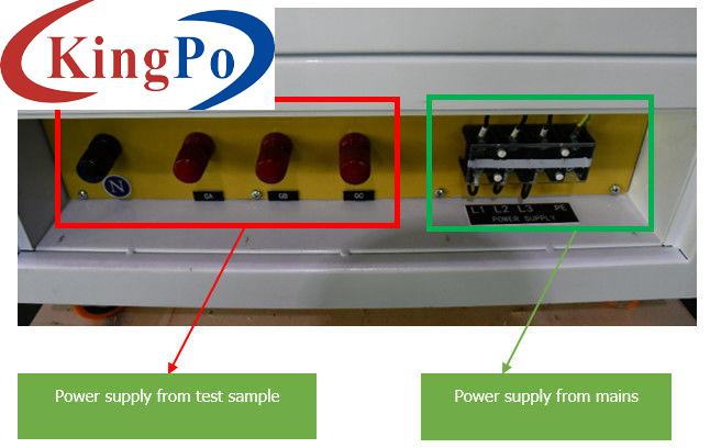
Power supply from test sample: If the power supply from the test sample is three phases, then all the GA, GB, GC and N terminals should be connected to test sample correspondingly (GA+GB+GC+N); if the power supply from the test sample is single phase, then one of the GA, GB, GC terminals plus N terminal should be connected to test sample correspondingly (such as GA+N terminals).
Power supply from mains: the power supply from mains should be three phases AC220V/60Hz, the power supply is for the control components of this load bank. Operator should remove the lower three wires from the lower three terminals, and wrap up them well. Then operator uses the power supply cord we’ve offered to connect to the mains (L1+L2+L3+PE). The load bank must be grounded reliably before use.
System composition
Load cabinet, resistive load, on-site data acquisition, manual load/unload control, electrical control part, heat sink and auxiliary control, etc.
Total discharge power
Resistive 30KW (designed according to three phase 220V/60HZ); at the same time meets 30KW single-phase 127V/60HZ (the current carrying capacity of the neutral line is the sum of the three-phase carrying capacity)
Resistive load binning
30KW total 6 gearsAny adjustment by combinations within 1KW-30KW power range (minimum step 1KW): 1KW, 2KW, 2KW, 5KW, 10KW, 10KW.
Test voltage
Three-phase AC220V/single-phase AC127V
Remark: Single and three-phase load test cannot be used at the same time
Test frequency
60HZ
Resistance tube
Each resistance element: insulation resistance above 500MΩ, withstand voltage AC2000V for 1-minute, high temperature resistance
Load characteristics
Resistive load
Contactor
China brand contactor
Breaker
China brand breaker
Heater
Wuxi Zhuxing
Power Factor
1.0
Load connection
Y
Loading accuracy
±3%;
Three-phase balance
The unbalance degree is less than or equal to 3%;
Way of working
Continuously working
Power supply
AC220VAC/60HZ/three-phase four-wire system; (reserved wiring terminals)
Cooling method
Forced air cooling
Way to control
Manual button control
Insulation class
F
Detection function
Real-time display of voltage, current, power, frequency, power factor, etc.
Load protection
Short circuit, over current, high temperature, low air volume and fan failure protection
Fault alarm
There is fan failure, load high temperature alarm
Load cabinet dimensions
L700mm×W800mm×H1000mm (L×W×H), with pulley (height 150MM)
Weight
172KG
Installation location
Indoor


