Products
IEC 60664-1 Clause 6.2.2.1 Impulse Voltage Generator 20KV High-Voltage Impulse
Products Description
IEC 60664-1 Clause 6.2.2.1 Impulse Voltage Generator 20KV High-Voltage Impulse
Product Information:
The Impulse Test Generator conforms to the standard requirements of IEC 60664-1 clause 6.2.2.1, etc.
It is used to verify that the appliances shall withstand the transient over-voltages to which they may be subjected. The impulse voltage test is a destructive test in which a breakdown occurs if the test specimen cannot withstand the applied voltage. When the sample breaks down, sparks and discharge sounds will be generated. The peak voltage of the instrument will drop significantly (close to zero) when it is no-load. When the same voltage is applied again, the above phenomenon will occur.
Feature:
An impulse voltage generator, also known as a lightning impulse generator or high-voltage impulse generator, is a specialized electrical testing device used to generate high-voltage impulses that simulate lightning strikes or other transient voltage phenomena. It is commonly used in electrical power systems, insulation testing, and research laboratories to assess the performance and withstand capability of electrical equipment and insulation materials under high-voltage impulses.
Key components and features of a typical impulse voltage generator include:
Charging System: The generator includes a high-voltage charging system that accumulates electrical energy from an external power source. This system typically consists of transformers, capacitors, and a charging circuit to store the required energy for generating the impulse voltage.
When operating an impulse voltage generator, it is crucial to follow safety protocols and guidelines provided by the manufacturer. Proper grounding, personal protective equipment, and adherence to testing standards, such as IEC or IEEE, are essential to ensure accurate and safe testing procedures.
Impulse wavefront time: 1.2 µs ± 30 %;
Half value of after wave time: 50 µs ± 20 %
Please note that the waveform should be checked on an external oscilloscope
Peak voltage
Impulse Voltage Generation Circuit: The generator employs a specialized circuit that rapidly discharges the stored energy to produce high-voltage impulses. This circuit may include switches, spark gaps, and resistors to control the discharge process and shape the impulse waveform.
Voltage Divider: A voltage divider is integrated into the generator to measure the generated impulse voltage accurately. The voltage divider consists of resistors and capacitors connected in a specific configuration to attenuate the high voltage and provide a representative voltage measurement for analysis.
Impulse Voltage Output Terminals: The generator is equipped with output terminals where the high-voltage impulses are applied to the test object or insulation material under evaluation. These terminals are designed to handle the high voltages and provide a safe and controlled connection to the test setup.
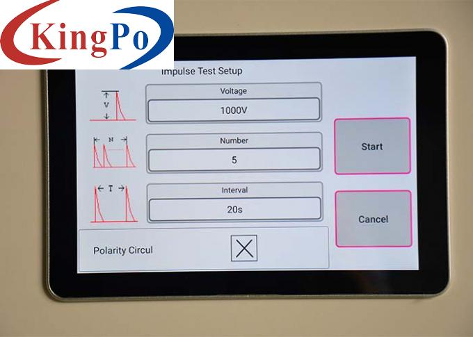
Control and Monitoring System: The generator features a control panel or system that allows operators to set and adjust the impulse parameters, such as voltage level, rise time, and duration. It may also include monitoring instruments to display and record the generated impulse waveform and provide real-time measurements.
Safety Features: Impulse voltage generators incorporate various safety features to protect both the operator and the equipment being tested. These features may include grounding systems, interlocks, and insulation barriers to prevent electrical accidents and ensure safe operation.
Impulse voltage generators are used to simulate high-voltage transients, such as lightning strikes, switching surges, or voltage spikes, which can occur in electrical systems. They are employed to test and evaluate the insulation strength, withstand capability, and reliability of electrical components, cables, transformers, surge arrestors, insulators, and other equipment.
Technical Parameters:
Model
SN1104-20KV
DC high voltage
20kV (Max) ±5%
Impulse voltage wave
Instrument internal resistance
2Ω ± 10%, 12Ω ± 10% and 500Ω± 10%
300V-20kV, Low: 300 V~ 2,500V; High: 2,500 V~ 20kV
Impact interval time
10~ 99s can be preset
Impact cycles
1 ~ 9999
Polarity
Positive and negative
Working power source
Rated voltage: ~ 220V±10%, 50/60Hz
Use environment
Temperature: 15°C-35°C, relative humidity 10%-75%
Dimension
600mm×570mm×1500mm
Weight
90 KG


