Products
IEC 60811 Resistance Of Insulations And Sheaths To Cracking Test Apparatus
Products Description
IEC 60811 Resistance Of Insulations And Sheaths To Cracking Test Apparatus
Standards & Clauses:
This test apparatus complies with the standards IEC 60811-509:2012, IEC 60811-508:2012, which specifies test methods for the polymer insulation and sheathing materials of electrical distribution cables and communication cables, including marine cables. It is suitable for the cracking and winding test of vinyl chloride wires and cables under high temperature conditions.
IEC 60811-508:2012 Electric and optical fibre cables - Test methods for non-metallic materials - Part 508: Mechanical tests - Pressure test at high temperature for insulation and sheaths
IEC 60811-509:2012 Electric and optical fibre cables - Test methods for non-metallic materials - Part 509: Mechanical tests - Test for resistance of insulations and sheaths to cracking (heat shock test)
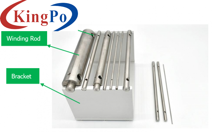
Structure:
Technical Parameters:
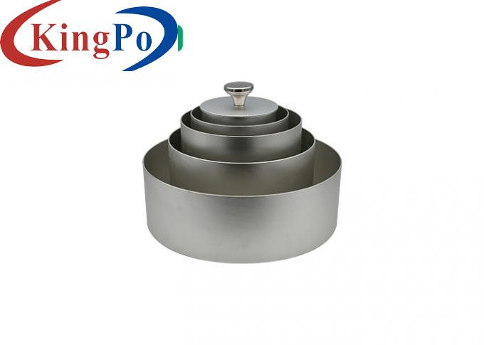
2, 4, 5, 6, 8, 9, 10, 13, 19, 40mm in total ten
Use Method:
1. Insulation Heat Shock Test
(1) Sampling: Two samples of appropriate length shall be taken for each insulated wire core to be tested, and the samples shall be taken from two places with an interval of at least 1m. The outer sheath, if present, shall be removed from the insulation.
(2) Sample preparation: The sample should be prepared by one of the following three methods:
A. For insulated wire cores whose outer diameter does not exceed 12.5mm, each sample is a section of insulated wire cores.
B. For insulated cores with outer diameter exceeding 12.5mm and insulation thickness not exceeding 5.0mm and all sector-shaped insulated cores, each sample should be taken as a narrow insulation strip, the width of which is at least 1.5 times the insulation thickness, but not less than 4mm. The narrow strip should be cut along the axis of the insulated core, and if it is a sector-shaped insulated core, it should be cut at the "back" of the insulated core.
C. For insulated wire cores with an outer diameter of more than 12.5mm and an insulation thickness of more than 5.0mm, each sample should be cut into narrow strips as specified in b, and then the outer surface of the narrow strips should be ground or cut (to avoid overheating) to a thickness of 4.0-5.0mm , the thickness shall be measured at the thicker part of the strip, the width of which is at least 1.5 times the thickness.
(3) Sample winding: Each sample should be tightly wound in a spiral shape on the test winding rod at ambient temperature, and the two ends should be fixed. The diameter of the test winding rod and the number of winding turns are specified as follows:
A. Table 1 applies to the samples prepared according to 1.2a; for flat cables or cords, the diameter of the test rod should be selected according to the size of its short axis, and the short axis should be perpendicular to the test rod when winding.
Table 1
D≤2.5
2.5<D≤4.5
4.5<D≤6.5
6.5<D≤9.5
9.5<D≤12.5
5
9
13
19
40
6
6
6
4
2
B. Table 2 applies to samples prepared in accordance with 1.2b and 1.2c, in which case the inner surface of the sample shall be in contact with the test rod.
Table 2
δ≤1
1<δ≤2
2<δ≤3
3<δ≤4
4<δ≤5
2
4
6
8
10
6
6
6
4
2
In the above table, the sample or thickness shall be measured with a vernier caliper or other suitable measuring tool.
(4) Heating and inspection: The sample wound around the test rod should be placed in an air oven preheated to the test temperature specified by the relevant cable product standards. Keep at the specified temperature for 1h.
After the sample has reached approximately ambient temperature, examine the sample still on the test rod.
(5) Evaluation of test results: When inspecting with normal vision or corrected vision without a magnifying glass, the sample should be cracked.
2. Sheath thermal shock test
(1) Sampling: Two cable samples of appropriate length should be taken for each sheath to be tested, and the samples should be taken from two places with an interval of at least 1m.
NOTE: All outer coverings should be removed.
(2) Sample preparation:
A. For the sheath with an outer diameter of not more than 12.5mm, each sample should be a piece of cable, but the polyethylene insulation and polyethylene sheath cables are removed.
B. For sheaths with outer diameter exceeding 12.5mm and thickness not exceeding 5.0mm and sheaths of polyethylene insulated cables, each sample shall be taken from a narrow strip on the sheath, the width of which shall be at least 1.5 times the thickness of the sheath times, but not less than 4mm, and the narrow strip should be cut along the axis of the cable.
C. For sheaths with an outer diameter of more than 12.5mm and a thickness of more than 5.0mm, each sample should be a narrow strip cut as specified in b, and then ground or cut on the outer surface of the narrow strip (to avoid overheating) to 4.0-5.0mm Thickness, the thickness shall be measured in the thicker part of the narrow strip, the width of the narrow strip is at least 1.5 times the thickness.
D. For flat cables, if the width of the cable does not exceed 12.5mm, each sample should be a complete cable. If the width of the cable exceeds 12.5mm, each specimen shall be a narrow strip cut from the sheath as specified in b.
(3) Sample winding: Each sample should be tightly wound in a spiral shape on the test rod at ambient temperature, and the two ends should be fixed. The diameter of the test rod and the number of windings are as follows: for the samples prepared according to 2.2a, see the provisions of 1.3a, and for the samples prepared according to 2.2b and c, see the provisions of 1.3b. The diameter or thickness of the specimen shall be determined with a vernier caliper or other suitable measuring tool.
(4) Heating and inspection: The sample wound around the test rod should be placed in an air oven preheated to the test temperature specified by the relevant cable product standards. Keep at the specified temperature for 1h.
After the specimen has reached approximately ambient temperature, examine the specimen still on the test bar.
(5) Evaluation of test results: When inspecting with normal vision or corrected vision without a magnifying glass, the sample should be cracked.

Maximum winding diameter
Φ12.5mm
Maximum winding width
72mm
Maximum winding length
200mm
Rolling rod size
Operation mode
Manual
Sample outer diameter: mm
Test winding rod: mm
Winding turns
Sample thickness δ: mm
Test winding rod: mm
Winding turns


