Products
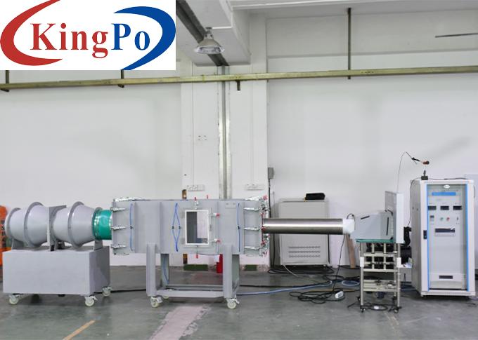
IEC 61591 2014 Range Hood Air Performance Air Volume Testing System For Pressure Efficiency Test
Products Description
IEC 61591: 2014 Range Hood Air Performance (Air Volume) Testing System For Pressure Efficiency Test
Standards For Range Hood Air Performance (Air Volume) Testing System:
GB/T14806-2017,GB/T1236-2017, GB32049-2015,ISO5801,IEC61591:2014
Product Overview For Range Hood Air Performance (Air Volume) Testing System:
This test system is based on the requirements of Chapters 5.3, 6.2 and Appendix A of the relevant GB/T 17713-2022 "Range Hoods and Other Cooking Smoke Suction and Exhaust Devices". R&D, design and production are carried out according to the requirements of the form, material, maximum dimensions and heaviest weight of the test product provided by the user. It is used to simulate the maximum full pressure efficiency test, working air volume test, maximum air volume and maximum static pressure test of the test product under specific environmental conditions, and verify whether the sample meets the limit values required by the standard.
The test system uses intelligent industrial control integrated system control, large-size computer displays and operation, automatic measurement, recording and automatic printing of test reports, and can analyze test results and test data to meet the needs of product development and production.
The test system can measure and plot the corresponding curves of static pressure and air volume, air volume and rotational speed, current, power, efficiency, etc. The test sample can also be tested in two states: inhalation and discharge. The test performance meets the latest standards for relevant products.
Principle and Layout For Range Hood Air Performance (Air Volume) Testing System:
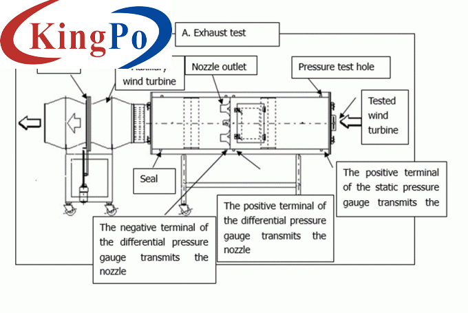
This solution adopts the blowing test mode, automatically turns on the nozzle combination according to the set air volume, and controls the air volume by steplessly adjusting the frequency of the auxiliary fan through the frequency converter. The middle of the air chamber is composed of a flow equalizing orifice plate, a nozzle, a starting actuator and a nozzle plate. The size of the air chamber interface is 600mm×600mm. This system automatically calculates the fan air volume by measuring the pressure difference before and after the nozzle. When the equipment is running, turn on the fresh air blower performance test device. The air volume of the auxiliary fan is controlled by controlling the opening and closing combination of the air chamber nozzle and the current frequency of the frequency conversion device. Use a high-precision micromanometer to measure the static pressure at the corresponding air volume, thereby obtaining the corresponding data of the air volume and wind pressure of the measured fan, and drawing the air volume and wind pressure curves.
Technical Parameters For Range Hood Air Performance (Air Volume) Testing System:
No.
Item
Content
The measurement accuracy of voltage, current and power is 0.2 level, and the digital display instrument
Range: Voltage AC 0-300V
Current AC 0--10A
Power 0-1000W
1) Maximum static pressure (static pressure value at zero air volume): Ps2n (max) Pa
2) Maximum air volume (air volume value at zero static pressure): Qv (max) m3 /min
3) Static pressure at specified air volume (7m3/min): Ps2ns Pa
4) Main motor input power at specified air volume (7m3/min): P W
5) Total pressure efficiency at specified air volume (7m3/min): η %
6) Air volume and pressure corresponding to the working air volume point (according to GB/T17713-20XX)
7) Maximum full pressure efficiency (according to GB/T17713-20XX)
8) Fluid dynamic efficiency (FDEhood): η % (including the corresponding optimal air volume, static pressure, and power)
9) Energy efficiency (EEIhood): η % (including corresponding lighting system power indication)
10) Pressure and air volume corresponding to the characteristic curves of 5Pa, 10Pa and 15Pa
Fully automatic and manual modes
1) There are two test methods for fully automatic testing, as follows: ① Fully automatic testing can be performed based on the maximum air volume point, that is, when the static pressure returns to zero, the maximum air volume can be read. Then it is divided into several air volume points according to the maximum air volume value, and corresponding tests of air volume and pressure are carried out to draw the air volume and pressure curve (P-Q curve). ② Fully automatic test based on the maximum air volume point and the specified static pressure value, that is, when the static pressure returns to zero, the maximum air volume is read first, and then the following test points are performed. Testing can be performed based on a pre-specified static pressure value or air volume value (up to 5 points can be specified for this static pressure value or air volume value). ③ When the prototype under test is not powered, specify the maximum air volume (i.e. the rated air volume of the prototype) to measure the static pressure. That is to measure the static pressure difference under the rated air volume (the static pressure difference between the air outlet and the air inlet of the tested prototype). This project is the resistance test (flow resistance test).
2) In the manual test part, there are four test methods, as follows: ① When powering the sample under test, specify the air volume to measure the static pressure, that is, test the static pressure value under a certain air volume. ② When supplying power to the sample under test, specify the static pressure measurement air volume, that is, test the air volume value under a certain static pressure. ③ When supplying power to the sample under test, specify the auxiliary fan frequency, and test the air volume value and static pressure value. ④ When no power is supplied to the sample under test, specify the maximum air volume (that is, the rated air volume of the sample under test) to measure the static pressure. That is to measure the static pressure difference under the rated air volume (the static pressure difference between the air outlet and the air inlet of the tested prototype). This project is the resistance test (flow resistance test). The above 4 manual tests are mainly used for motor performance R&D testing.
The device is composed of ontology and calculation system
1. Ontology device
1) Air chamber The cross-sectional dimensions of the air chamber shall not be greater than: length 1700mm×width 500mm×height 500mm. Weight shall not be greater than: 300kg.
2) Auxiliary fan diagonal flow fan meets the maximum 25m 3/min 1000Pa and is controlled by a frequency converter. Weight not greater than: 90kg
3) Electrically adjusted damper damper The damper damper is controlled and adjusted by a variable speed motor. Speed control of the damper: high speed and low speed control in forward and reverse directions (DA).
4) Nozzles: Use 4 specifications of nozzles, 8 in total (1 each for φ15, 25, 30, 50, 4 for φ60). Applicable range of each nozzle
The nozzle is opened by manually pulling out the nozzle plug. The nozzle chamber must be equipped with a transparent door that can be opened and closed, and provide sufficient space for manual operation. Special note: Opening the nozzle cover needs to be opened manually, according to the wind tunnel manufacturing requirements in Figure A.3 and Figure A.4 of GB/T1236-2017 or GB/T14806-2017. Only specified flow stabilizing devices can exist inside the wind tunnel, and other related components that will affect the flow coefficient cannot be installed. (For example, installing a cylinder head or motor cover in front or behind each nozzle in order to automatically plug the nozzle cover. This will cause a non-linear flow coefficient change that cannot be corrected)
2. Calculation system
1) Electric control cabinet Dimensions of the electric control cabinet: length 600mm × width 600 mm × height 1500mm. Each control circuit, data acquisition board, frequency converter, differential pressure transmitter and other instruments are arranged and installed in the cabinet.
2) Data acquisition board model, etc.
3) Software
① The software program used is provided by being loaded into the CPU.
The operating system is Windows7.
Computers and peripheral equipment: host, display screen, printer
② Functional requirements of software
☆ Execute the program through human-machine dialogue.
☆Use the keyboard to enter the specifications and test conditions of the fan under test.
☆ When automatically measuring pressure and air volume, use the keyboard to enter the number of selected measuring points. The number of measuring points for air volume is equally divided according to the maximum air volume. The number of measuring points shall be no less than 25. Current and power can be entered using the keyboard. Select the nozzle to be inserted according to the instructions on the screen (manual operation). The operation of the auxiliary fan and damper and the measurement of static pressure at each air volume are all performed automatically.
☆ After the test is completed, the measured values and basic data can be saved in any disk.
☆ After the test is completed, the measured data and characteristic curve will be printed out by the printer.
☆ It has the function of automatically adjusting the coordinate ratio of the performance curve screen. Make the screen representation clearer and more reasonable. ☆ The unit of air volume during measurement can be m3/min, m3/h, CFM.
☆ On the same graph, the composite curve of each test item can be drawn. The composite curve is identified by six symbols: ○, □, ×, △, ◇, and ◎. In addition, the fan model is also shown on the diagram together with the identification symbol.
☆ In addition to P-Q's automatic test, it also comes with software for measuring static pressure at any air volume point.
③ Measured values, keyboard input values, calculated values
☆ Volume flow calculated value
☆ Static pressure measurement value
☆ Speed measurement value
☆ Current measurement value
☆ Efficiency Calculated Value The abscissa of the graph is volume flow, and the axis can represent the following 5 parameters: static pressure, speed, current, electricity, efficiency
④ Measurement of differential pressure and static pressure. Because turbulent flow, differential pressure and static pressure change with time, the following processing is done by computer. After the positions of the auxiliary fan and damper are set, wait a few seconds for stabilization and then read the data 10 times to calculate the nozzle differential pressure, static pressure and the average value of each converter. At subsequent measurement points, the auxiliary fan and damper are automatically adjusted.
⑤ When selecting the "Operation Panel Adjustment" menu, you can test the operation of the operation panel. When malfunction is found during the test, this menu can be used to perform individual action tests on the auxiliary fan, damper, etc.
⑥ Manual Manual: Use the keyboard to input the air volume and static pressure test method of the measuring point. Select "Manual P-Q measurement" in the menu. The data measured in manual mode are processed in order of air volume (from small to large) and a P-Q curve is drawn.

Power supply
AC380V 50Hz 5kVA
Applicable products
Range hoods, ventilation fans, bathroom heaters, heaters, cooling fans, axial fans, air purifiers, etc.
Test items and scope

Test environment
20℃±5℃ Humidity: 30%--80% Atmospheric pressure: Normal
Measuring air volume range
(0.06-25 cubic)/minute, (3.6-1500 cubic/hour)
Static differential pressure
0-1500 Pa ≤±1% or ±1.5Pa (when the measured pressure is less than 100Pa, the basic error is less than ±0.4Pa)
Electrical parameters
Rotating speed
0-5000 rpm ±5RPM digital display
Air temperature
0—50℃ ±0.5℃
Air humidity
(5~99)%R﹒H ±5%
Frequency conversion power supply
5KVA
After the test is completed, the computer can automatically calculate the measurement results
Measurement curve
The corresponding curves of static pressure and air volume, air volume and rotation speed, current, power, efficiency, etc. can be measured and plotted. The test sample can also be tested in two states: inhalation and discharge.
Test mode
Device composition


