Products
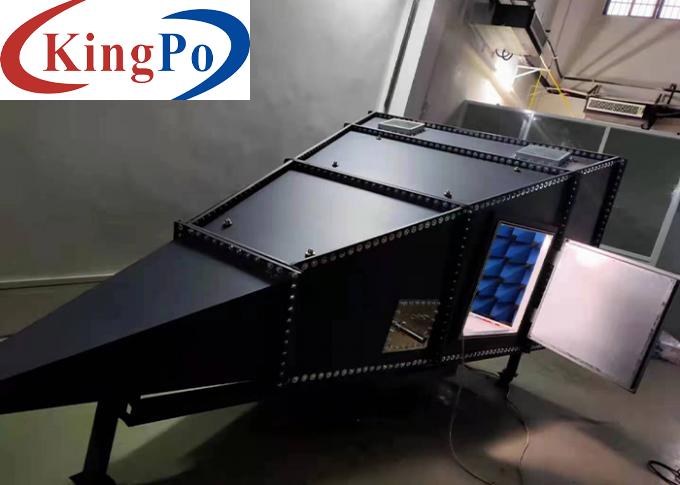
IEC 61967-2 Chip Test Integrated Circuit Gigahertz Transverse Electro Magnetic Cell
Products Description
IEC 61967-2 Chip Test Integrated Circuit Gigahertz Transverse Electro Magnetic Cell
Product Overview For Chip Test Integrated Circuit GTEM Cell:
GTEM (Gigahertz Transverse Electro Magnetic) Gigahertz Transverse Electromagnetic Wave Cell is a single-port closed waveguide with a frequency up to 20GHz.
Using GTEM (Gigahertz Transverse Electromagnetic Wave) for electromagnetic compatibility testing is a new measurement technology developed in the field of international electromagnetic compatibility in recent years. Due to GTEM's broadband characteristics (from direct current to microwave) and low cost (only a few percent of the cost of an anechoic chamber), it can be used for electromagnetic radiation susceptibility tests (EMS tests, sometimes called immunity tests). It can also be used for electromagnetic radiation test (EMI test) and the equipment used (compared to the test in the anechoic chamber) has simple configuration. The cost is cheap and it can be used for fast and automatic testing, so it has been paid more and more attention by relevant international and domestic people. Among them, especially for the testing of small equipment, the measurement solution of the GTEM cell is the best test solution with the best performance-price ratio.
Test Standards For Chip Test Integrated Circuit GTEM Cell:
GTEM cell (Gigahertz Transverse Electro Magnetic) EMC standard of GTEM cell:
EMI standards: Establish a common basis for evaluating the radiated emissions of electrical and electronic equipment (components).
IEC 61967-2 Measurement of electromagnetic emission from integrated circuits 150kHz to 1GHz Part 2: Radiated emission measurement TEM cell method.
EMS Standard: To establish a common basis for evaluating the ability of electrical and electronic equipment to resist radiated electromagnetic field interference.
IEC 62132-2 Measurement of Electromagnetic Immunity of Integrated Circuits 150kHz~1GHz Part 2: TEM and GTEM Cell Method.
IEC 61000-4-20, EN 61000-4-20
IEC 61000-4-3, EN 61000-4-3
IEC 61000-6-3, EN 61000-6-3
IEC 61000-6-4, EN 61000-6-4
ISO 11452-3, SAE J1113-24
Composition For Chip Test Integrated Circuit GTEM Cell:
GTEM can be regarded as a spatial expansion of the 50Ω coaxial cable in order to accommodate the measured object. The core wire of the coaxial cable is expanded to be the core plate of the GTEM cell, and the sheath of the coaxial cable is made into the shell of the GTEM cell. The characteristic impedance inside the GTEM cell is still designed to be 50Ω. In order to prevent the input electromagnetic wave from being reflected at the end of the internal cavity, the end of the core board is connected to a broadband matching load, and a wave-absorbing material is placed at the end of the cavity. In order to absorb the electromagnetic waves emitted to the end.
The transverse electromagnetic wave propagates along the core plate, and the electric field intensity generated is proportional to the voltage applied on the core plate. The strength of the field at different positions also depends on the height of the core board (the distance between the inner conductor and the ground), the closer to the partition, the stronger the field strength.
Technical Parameters For Chip Test Integrated Circuit GTEM Cell:
Main performance indicators:
Frequency range: DC-6GHz
Input impedance: 50Ω±5Ω (typical value: 50Ω±2Ω)
Voltage standing wave ratio: ≤1.75 (typical value: ≤1.5)
Maximum input power: 1000W
Cell dimensions of outer: 4.0m x 2.2m x 2.1m (L x W x H)
Maximum electronic partition height: 750mm
±3dB field uniformity test area: 350 mm x 350 mm
Maximum recommended EUT test area: 67.5 x 67.5 x 49cm
Weight: 500kg
Frequency range
80MHz-1000MHz
Output power
70W
Gain
+49dB
Type
A
Linear power gain flatness
Maximum ±3dB
I/O impedance
50ohm
Input VSWR
Maximum 2:1
Input power
Maximum +0dBm
Harmonic distortion
H2, H3<-20dBc of output power at 1dB compression point limit
RF input interface
N-type terminal female (front panel or rear panel), other interfaces can be customized
RF output interface
N-type terminal female (front panel or rear panel), other interfaces can be customized


