Products
IEC 62752 Clause 9.34 Vehicle Drive Over Testing Machine For Plug Or Vehicle Connector Test
Products Description
IEC 62752 Clause 9.34 Vehicle Drive Over Testing Machine For Plug Or Vehicle Connector Test
Product information:
The test equipment is used to check whether a plug or vehicle connector shall have adequate resistance to damage from being driven over by a vehicle, unless it is provided with a cable management system which prevents the accessory from being left on the ground. It is required by IEC 62196-1:2022 clause 33, IEC 62752:2016 clause 9.34, etc.
Test principle:
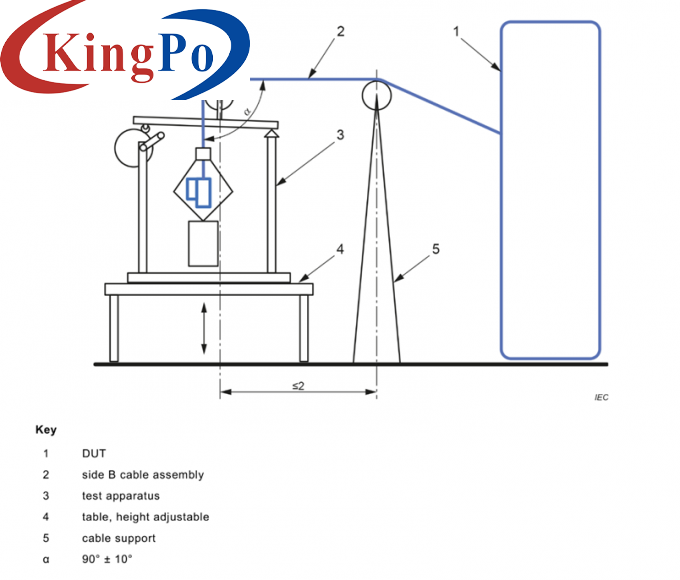
Accessories wired with the minimum size cable of a type recommended by the manufacturer shall be placed on a concrete floor in any normal position of rest. A crushing force of (5000±250) N or (11000±550) N shall be applied by a conventional automotive tire, P225/75R15 or an equivalent tire suitable for the load, mounted on a steel rim and inflated to a pressure of (2.2±0.1) bar. The wheel is to be rolled over the vehicle connector or plug at a speed of (8±2) km/h. The accessory is to be oriented in a natural resting position before applying the force in a different direction for each sample. The accessory under test shall be held or blocked in a fixed position so that it does not move substantially during the application of the applied force. In no case is the force to be applied to the projecting pins.
Applied standard & clauses:
IEC 62196-1: 2022 clause 33.
IEC 62752:2016 clause 9.34.
Structure:
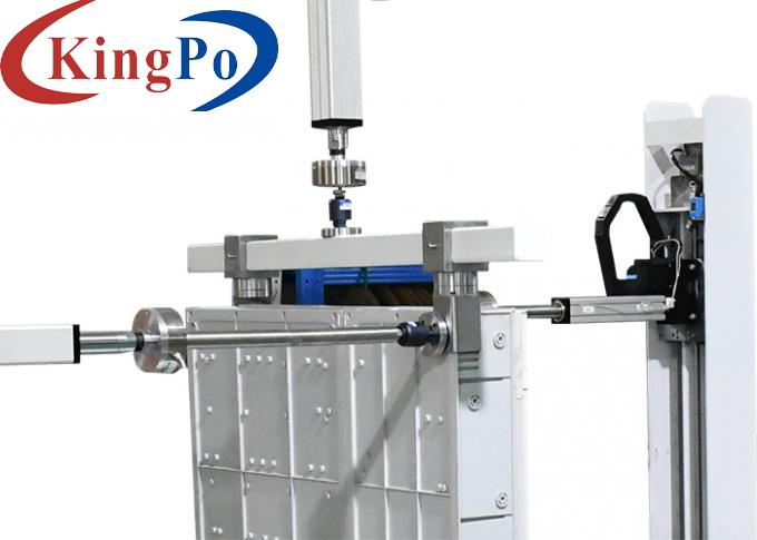
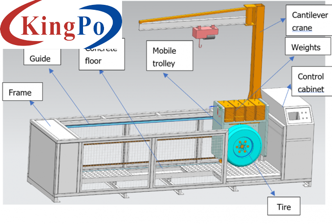
The entire equipment adopts a cold-rolled steel plate protective box structure design. The surface of the box is treated with Teflon paint. The bottom of the box is covered with simulated cement floor. The rolling mechanism can simulate a car tire sliding up and down freely after rolling over an object. The charging pile plug bear the same pressure. The driving device drives the rolling mechanism to achieve forward and backward rolling movements. The main components are made of stainless steel and aluminum parts. Ensure that the tire is rolling over the sample under normal rolling conditions. The main features are as follows:
1. The equipment chassis is equipped with a protective cover to ensure the safety of the test process. The bottom of the box is equipped with shock-absorbing foot pads and a pulley structure for easy installation and disassembly. Guided by heavy-duty slide rails, the roller set slides. The power combined with a high -power motor combined with the turbine reducer, driving the spindle rotation, and the test speed is promoted for crushing test. The specimen fixing device is equipped with an installation fixture for functional box of the specimen to meet standard requirements.
2. The drive over pressure adjustment device is designed with an upper and lower adjustable structure. The tires, upper and lower sliding frames and counterweights borne by the specimen are the total weight of the test.
3. The equipment adopts the working mode of front and rear tire drive: the drive over direction is driven by the forward and reverse rotation of the motor to drive the tire rolling. Keep the specimen stationary. It can simulate the reciprocating rolling of car tires in the most realistic way. Effectively simulate rolling of the specimen.
4. The control system is an independent organization. The host machine is controlled by PLC and operated by touch screen. There are fixed mounting holes and cable openings at the bottom for easy fixing and connection.
Technical Parameters:
A. Crushing force (5000±250) N
B. Crushing force (11000±550) N
Using weights, the force range is adjustable from 5000N-11000N, and the weights are loaded and unloaded by cantilever crane.
1. Equipped with one P225/75 R15 tire and one matching wheel hub, a set of tire inflation devices (inflation interface and air pressure gauge, for 5000N test)
2. Equipped with 11000N load-bearing tire and a matching wheel hub.
3. The wheel load shall be mounted on a steel rim
Base plate with cement/concrete floor, can be equipped with sample fixing clamp.
The whole machine is equipped with a protective fence to prevent the wheels from accidentally deflecting and prevent mechanical injuries to personnel.
With leakage protection switch.
With motor overload protection.
Power supply: AC400V+10 % and – 6%, 50Hz ± 1%.
Overall dimensions: approximately W4700*D1300*H3000mm; weight: approximately 2400kg

Test station
Single station
Equipment placement mode
Floor standing
PLC control system
Operation mode
Manual or program-controlled operation, can be selected
Drive over power system
Motor plus worm gear acceleration and deceleration
Drive over stroke
0~2.0m
Load Carrying
Force sensor
Will be provided with an external precision force sensor to measure the total force from tyre, load, upper and lower sliding frame, power system and counter weight before testing.
Drive over speed
(8±2)km/h, speed adjustable
Drive over method
It is driven by a linear motor module to simulate the forward and backward reciprocating motion of rolling tires. This simulates the damage caused by accidental crushing of the plug of the charging pile when the car is moving forward or reversing in reality.
Drive over force adjustment
Drive over tires


Drive over tire pressure
(220±10) kPa
Load bearing base plate


Deceleration method
Our company has designed a braking mechanism to prevent rigid collisions.
Safety protection

Usage environment


