Products
Max. 100A Switch Life Tester IEC 60884-1 Figure 12 Screwless Terminals Deflection And Voltage Drop Test Device
Products Description
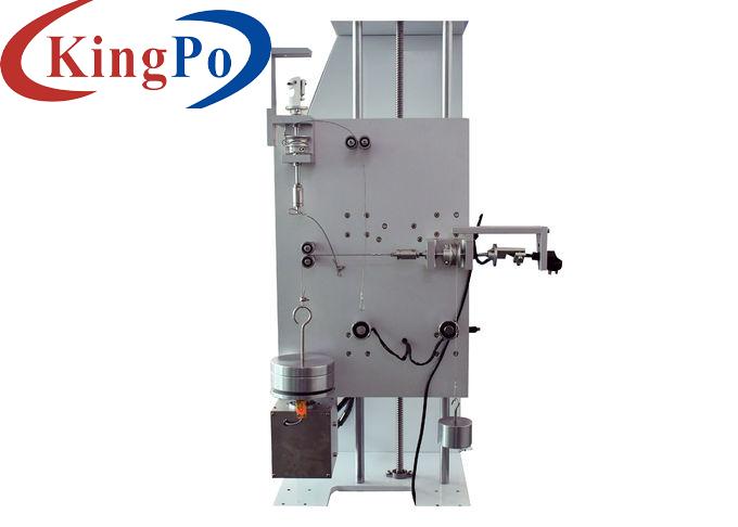
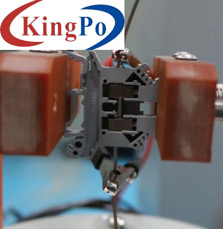
IEC 60884-1 Figure 12 Screwless Terminals Deflection and Voltage Drop Test Device
Standard: IEC60884-1 clause 12.3.12, Figure 12.
Application: It is used to check screwless terminals shall be so designed that the connected rigid solid conductor remains clamped, even when it has been deflected during normal installation, for example, during mounting in a box, and the deflecting stress is transferred to the clamping unit.
Test sample: Plugs and socket-outlets screwless terminals.
Technical Parameters:
2. Placed the screwless terminals into the fixture, the perpendicular of the conductor should be coincided with the center of the base. The upper conductor passes through the holes of the force plate, the lower conductor should not touch the floor , then clamp the terminal parts.
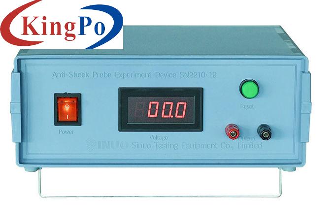
4. The red clip of the current output of the voltage drop tester is clamped on the upper conductor, and the red clip of the voltage drop measurement input is clamped in the position near the terminal, then hang on the weight.
5. clamped on the lower conductor, and the black clip of the voltage drop measurement input is clamped in the position near the terminal.
6. Rotate the base turntable, each rotation is 30 °, the starting point should be where the conductor in a natural state.
Parameters Name
Parameter Data
Power supply
Match client's local power supply conditions
Deflection angle
0-360°
Deflection direction
In any of the 12 directions differing from each other by 30°±3°
Deflection force
0.25N, 0.5N, 1.0N
Force applied direction
Perpendicular to the undeflected conductor
Test current
Max.100A

3. Loose the fastening handle of the support column and move the crossbar up and down, so that the distance from the end of the terminal to the force plate is 100 mm. The crossbar must be kept horizontal.
