Products
SBL Load Bank IEC 60669-2-1 Figure 103 Load B 3 Channels 10 Loads
Products Description
SBL Load Bank IEC 60669-2-1 Figure 103 Load B
Equipment Overview:
This SBL load bank is used to test the on-off capability of the switches intended for self-ballasted lamp loads. The switches used to control the self-ballasted lamp should withstand the electrical and thermal stresses that occur when controlling the LED circuit without excessive damage or other harmful effects. The purpose is to check whether the switch has continuous arc flashing, whether the contacts are welded, and whether the contacts are closed or disconnected for a long time, and whether there is excessive wear and other harmful consequences. This load cabinet fully meets the load requirements of clause 19.3 load B of IEC 60669-1 and clause 19.109 of IEC60669-2-1 for the switches intended for self-ballasted lamp loads.
Main Technical parameters:
Approximate dimensions: width 770mm × width 960mm × height 1700mm, the color of the frame is blue, the side panels are light white, and the upper front is the operation control panel. On the panel, there are power supply control switch, product test voltage and power display instruments, alarms, touch screen, etc., inside the upper part of the cabinet, there are resistor and capacitor load combinations, AC contactors, and relays, on the lower part of the cabinet, there are connection terminals, which are connected with the sample through the wires to output current and provide load during the detection process.
1) Power supply: match client's local power supply requirements with ground wire.
2) Digital display voltage value: range 0~300V, accuracy 0.5 level.
3) Digital display power value: range 0~1KW, accuracy 0.5 level.
4) Number of output channels: 3 channels, namely 3 independent test stations.
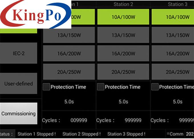
5). Each channel has selection buttons with pre-set test modes, such as IEC-1 test modes (as per IEC 60669-1:2017) : 100W,150W, 200W, 250W; IEC-2 test modes (as per IEC 60669-2-1: 2002/AMD2: 2015): 100W, 150W,200W, 250W (these four test modes are in IEC-1 interface), 30W, 60W, 300W, 350W (these four test modes are in IEC-2 interface) and 15W, 400W in the User-defined interface shown as User-1 and User-4, and the remaining selection buttons in the User-defined interface shown as User-2 and User-3 can be defined by user by inputting the values through the touch screen interface.
6) The input voltage is adjustable to ensure the test voltage.
7) All working parameters are set, including W, Ipeak, I²t and impulse current waveform.
8), Ipeak, I²t and real-time waveform of impulse current are directly displayed on the touch screen interface, and the numbers of random impulse waveforms will be counted.
9) Each set of equipment provides a closing control device (the touch screen selects the "CAL" function), and it is conducted at a 90-degree angle each time. This function can be used for the initial adjustment of the equipment and the measurement calibration.
10). With long-breaking/long-conduction protection functions, the protection time can be preset from 1 to 99S, and it will alarm when it is under protection situation.
11). Use environment: temperature 5~40℃, relative humidity 20~90%RH, atmospheric pressure 80~106kpa; no severe vibration, no electromagnetic interference, no dust, corrosive gas, and a place with good heat dissipation.
Total default 10 SBL loads as listed in following table 108:
Ipeak
A
Distribution system: 220/380, 230/400/ 240/415
I2t
A2s
Distribution system: 220/380,
230/400/
240/415
What's advantages of our SBL load bank?
1. This load cabinet has been preset with the load conditions required by the standard before leaving the factory. As long as the test voltage is adjusted to 230~ to 250V~, the operator presses the corresponding button on the touch screen with the same rated current and power of the switch to be tested, then its rated power, impulse waveform, Ipeak and I²t meet the corresponding requirements of the standard.
2. The operation is convenient and intuitive, the input voltage and output power are digital displayed, the current impact Ipeak current value and I2t energy value can be observed on the touch screen, and the numbers of random shock waveforms will be counted.
3. With 3 stations, 3 switches with different parameters can be tested at the same time.
4. With calibration mode and calibration dedicated port, built-in 90-degree closing plate, it is convenient to measure the output waveform, Ipeak current value and I²t energy value, which fully meets the requirements of the standard for equipment calibration.
5. This equipment is equipped with an automatic intelligent voltage regulating and stabilizing device (this device is especially suitable for use at night when the voltage rises), it can reach the required voltage value of 250V~ without needing to connect an external manual voltage regulator.
6. Built-in 10 loads as per requirements of EC60669-1:2017 clause 19.3 and IEC60669-2-1: 2015 figure 103, clause 19.109. Operator can select the corresponding load directly, no need to process complex adjustment. The operation is easy and accurate.
Rated Power (W)
15
22
0.08
30
41
0.3
60
73
1.2
100
108
2.8
150
142
5.5
200
170
9
250
192
13
300
209
16.5
350
223
20.5
400
235
24.5

