Products
Switches Intended for Self-ballasted Lamp Loads Automatic Breaking Capacity Test System
Products Description
Automatic Breaking Capacity Test System for Switches Intended for Self-ballasted Lamp Loads
Standards & Clauses:
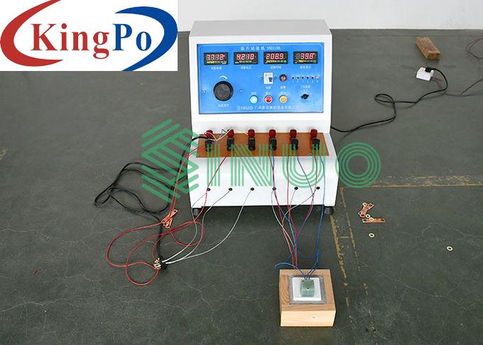
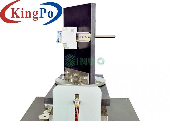
This system is designed and manufactured according to the standard of IEC 60669-1:2017 clause 19.3 and IEC 60669-2-1:2015 clause 19.109. It is a fully automatic test system based on the test readability of a switch with a rated voltage of 250V, including an intelligent industrial control system (built-in oscilloscope), a switch endurance test machine, and a self-ballasted lamp load cabinet. (The switch with rated voltage of 130V needs to be separately configured with self-ballasted lamp load box).
Samples and Restrictions:
Switches intended for self ballasted lamp loads
Application:
This device is suitable for breaking capacity and normal operation life test of switches intended for self ballasted lamp loads. Switches intended for self ballasted lamp (SBL) loads shall withstand, without excessive wear or other harmful effect, the electrical and thermal stresses occurring when controlling self ballasted lamp circuits. To verify whether the switch has sustained arcing nor welding of the contacts occur, any contacts adhesion phenomenon or long term closure or disconnection phenomenon, to test whether excessive wear or other harmful consequences.
Test Principle:
IEC60669-1:2017 and IEC60669-2-1:2015, only for switches with a rated voltage of 250V.
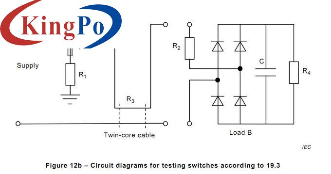
The load box circuit shall be in accordance with Figure 12b and clause19.3, with rectifier bridge and capacitor.
The value of R2 and C in load B shall be chosen in order reach the values (±5%) for I peak and I2t as given in the Table 19 when the switching contact closes at 90°±5° phase-angle. The value of R4 shall be chosen to reach current in amperes to reach the corresponding SBL power as given in Table 19.
The value of R2 and C in load B shall be chosen’ mean that the resistance R3 and the capacitor C is adjustable;
Technical Parameters:
IPC: IPC-810E
Configuration software: E5
Oscilloscope: Tektronix or Agilent
Acquisition module: multiple
Dimensions: WDH=600*500*1450mm,
surface electrostatic powder spraying
Station: 3 independent test stations
Control system: 7-inch color LCD touch screen +PLC+ servo motor, It has a communication interface, which is convenient for online use or communication with other devices (such as various loads), enabling data collection and statistics.
Test stroke: 0.1~100mm, can be preset
Test speed: 0.1~200mm/s, can be set
On/Off time: the ‘on’ period shall be(25+5 0)% of the total cycle and the ‘off’ period (750 -5)%, 0.1~99.9 can be preset
Operating rate: 3 - 40 times can be set, associated with test stroke, test speed and on/off time setting
Alarm detection: Built-in detection circuit, when the product is detected to be unqualified, there is an audible and visual alarm, and there are text prompts:
Load connection port: different test loads can be connected as needed, such as tungsten filament lamp load, externally ballasted lamp load, TV load, inductive load, capacitive load, motor load and so on.
Dimension:W1250mm×D650mm×H1150mm;
Weight:100kg.
Voltage display value:Range 0 ~ 300V, precision 0.5,
Power display value:0~9KW, precision 0.5
Output channel: 3 channels (two channels are 250W and the other channel is 400W)
Switch rated voltage: 250V ~, the input voltage is adjustable,All operating parameters are set at 250V~, including W, Ipeak, I2t, and inrush current waveforms.
Rated current 10A, 13A, 16A, 20A four optional
Each device provides a closing control device (touch screen select "calibration" function),each time is in the 90 degree angle conduction, this function can be used for initial equipment calibration and measurement verification.
With long on/ long off protection function, the protection time of 1 ~ 99S can be preset, shutdown alarm protection.


Values (±5%) for I peak and I2t as given in the Table 19 when the switching contact closes at 90°±5° phase-angle’ mean that the integral of the calibration I peak and I2t is obtained at the 90 ° closing, and the equipment must have a 90 ° closing control. The 90 ° closing control does not work during normal testing, and the on/off of the switch is turned on at a random phase angle as in daily operation;
‘The value of R4 shall be chosen to reach current in amperes to reach the corresponding SBL power’ mean that this rated current is not the rated current of the switch, but the corresponding power of Table 2.
Item
Content
Power
Match client's local power supply
Intelligent industrial control system
Switch Endurance Test Machie
Self-ballasted Lamp Load Cabinet
Use environment
Temperature 5 ~ 40 °C, relative humidity 20 ~ 90% RH, atmospheric pressure 80 ~ 106kpa. No severe vibration, no electromagnetic interference, no dust, corrosive gas, good heat dissipation.

