


IEC62368 Three Vertical Bar Signal
1 Overview
1.1 Product Profile
The product is used for the testing of digital TV, providing a test signal for television test experiments.The product can produce the video test signals for the CVBS, YPbPr and HDMI interfaces to meet the requirements of the TV test.
1.2 Application field:
1. TV safety test experiment;
2. TV electromagnetic compatibility test experiment;
3. Other related test experiments of TV sets;
1.3 Functional Features:
(1) It includes three interface types: CVBS, YPbPr and HDMI;
(2) Support for PAL and NTSC calibration and clearing video format;
(3) Support for 1280720p 50Hz, 1280720p 60Hz, 19201080i 50Hz, 19201080i 60Hz, 19201080p 25Hz, 19201080p 30Hz, 19201080p 50Hz, 19201080p 60Hz HD video formats;
(4) Support for ultra-HD (4K) video format of 3840 2160 25p and 3840 2160 30p;
2 Front panel description
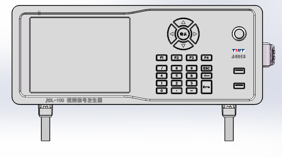
1System display
Display the system control software interface, with a touch screen function, for setting the selection of the system signal, the video format, and the setting of the digital TV modulation signal parameters.
2key
It is composed of navigation keys (up and down, etc.), digital keyboard and function keys to facilitate users to operate and control the software.
4USB joggle
Easy for users to connect to the mouse, keyboard, U disk and other external devices.
5power key
The control system switches and switches.
3 Rear panel description
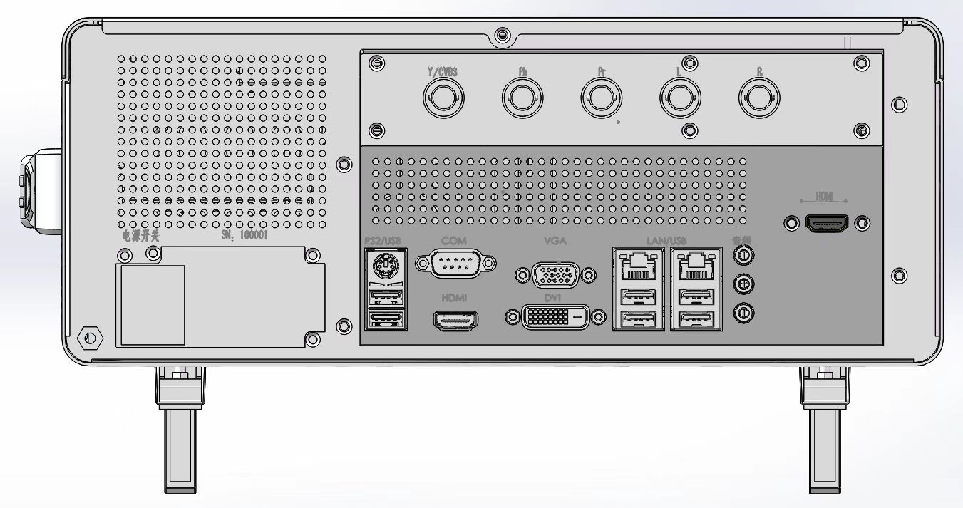
1The Y / CVBS, Pb, and Pr interfaces
The output interface of analog TV composite signal and chromatic component signal, where Y / CVBS interface outputs composite signal (CVBS) when the signal formats are PAL and NTSC, and the luminance signal in chromatic signal (Y) in other formats.
2L, R joggle
Audio output interfaces, L and R represent the left and right channels, respectively.
3HDMI joggle
Digital video signal output interface.
4System peripherals interface
Easy for users to connect to the monitor, mouse, keyboard, U disk and other external devices.
5System power supply interface and switch
Connect and control the system power supply.
3 Technical indicators
| interface type | project | scope | metric |
| CVBS | intensity level | (0~700)mV | ±(2%X+6mV) |
| Color level | (0~885.1)mV | ±(2%X+6mV) | |
| chrominance phase | (0~360)° | ±2° | |
| YPbPr | Brightness signal output level (Y) | (0~700)mV | ±(2%X+6mV) |
| Chromatic difference signal output level (Pb, Pr) | (-350~350)mV | ±(2%X+6mV) |
Annex 1 Methods of system software
RDL-100 Video Signal Generator System Control Software V1.0 Operating Instructions.
Write the purpose
The purpose of this document is to introduce the operating instructions and operation steps of the RDL-100 video signal generator system control software V1.0 for easy user use.
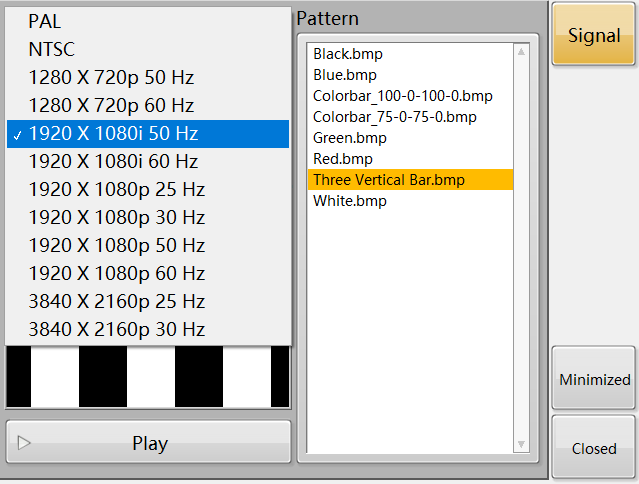
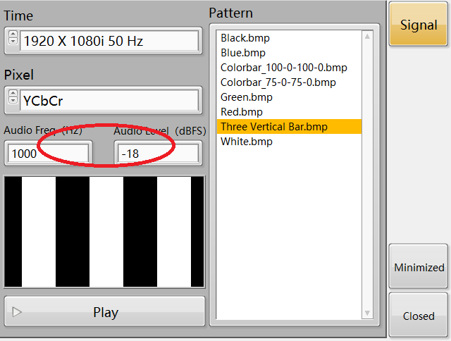
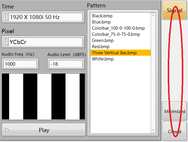
The RDL-100 video signal generator system control software V1.0 is opened displays the main control and display interface in Figure 1, including 10 controls of Time, Pattern, Pixel, Audio Freq, Audio Level, Preview, Play, Signal, Minimized, and Closed.
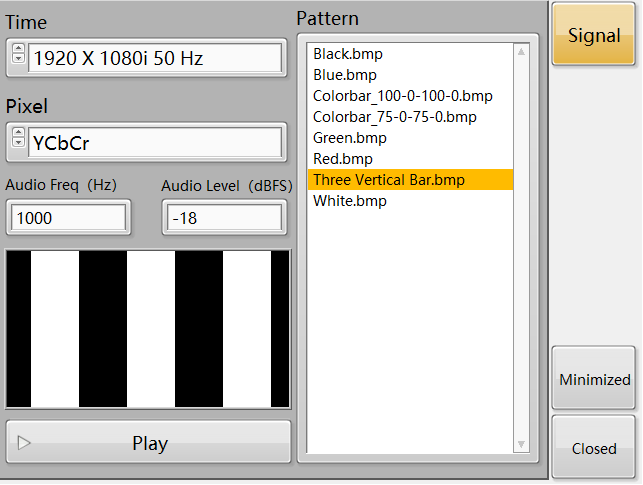
graph 1
Time control
The control is shown in Figure 2 to display the video format for users to choose, and the interface is shown in Figure 3.
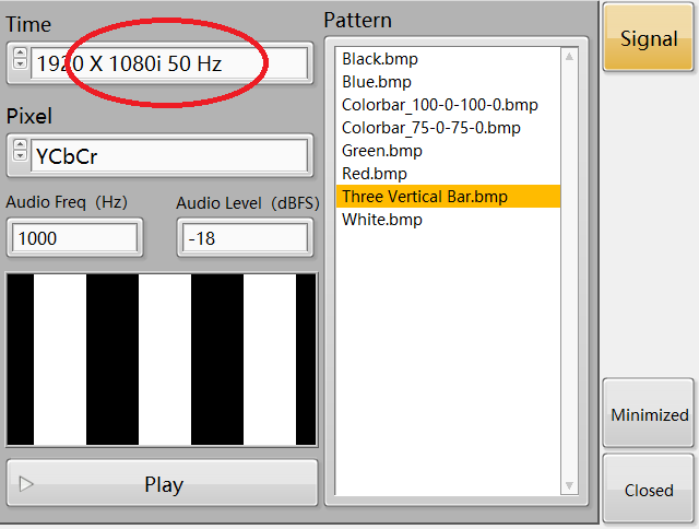
graph 2
graph 3
The Pattern control
The control in FIG. 4 serves to display the video test signal for the user to choose.
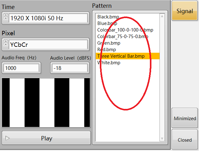
graph 4
Pixel control
The control is shown in FIG. 5, which is to display the pixel sampling mode for users to select, and click the interface in FIG. 6.
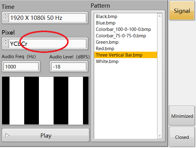
graph 5
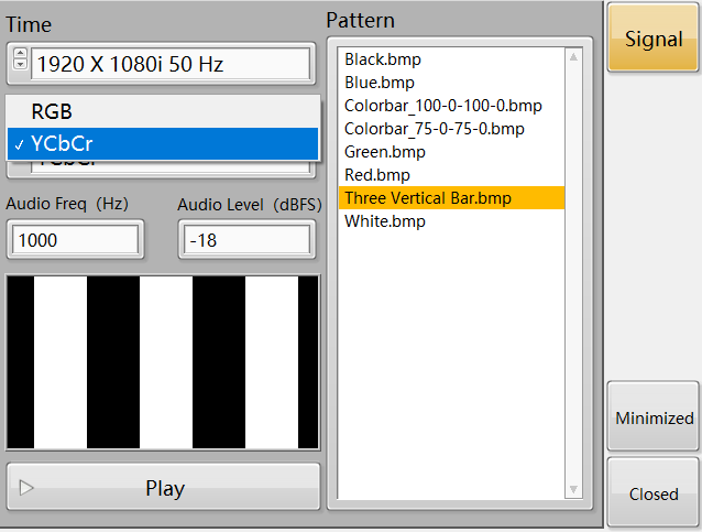
graph 6
The Audio Freq and the Audio Level controls
The control is shown in FIG. 7 to set the frequency and level of the accompaniment.
graph 7
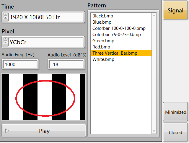
The Preview control
The control is shown in FIG. 8 to preview the selected video signal for the user reference.
graph 8
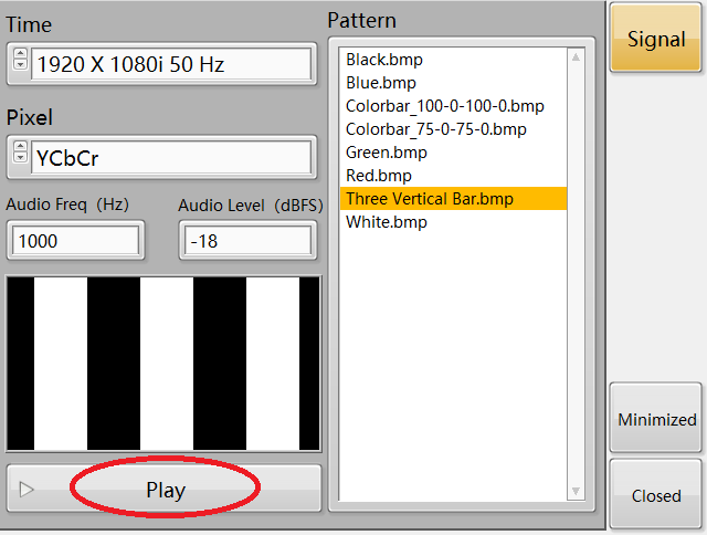
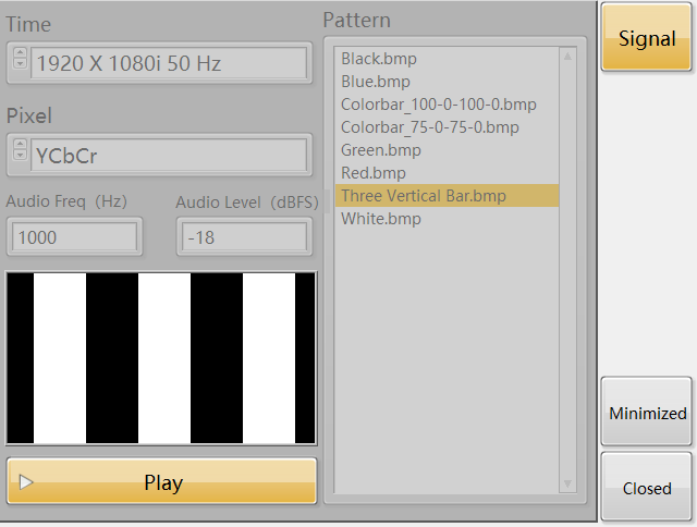
Play control
The control is used in FIG. 9 to play and stop playing the video signal. When the button is playing the video signal, stop playing the video signal when the button is extinguished. When playing the video signal, the Time, Pattern, Pixel, Audio Freq and Audio Level controls are prohibited, and the interface is shown in FIG. 10.
graph 9
graph 10
The Signal, Minimized, and Closed controls
The control appears in Figure 11. The Signal control has no substantive effect, and the Minimized and Closed controls function to minimize the interface and close the software, respectively.
graph 1
Three Vertical Bar Signal IEC62368 Three Vertical Bar Signal
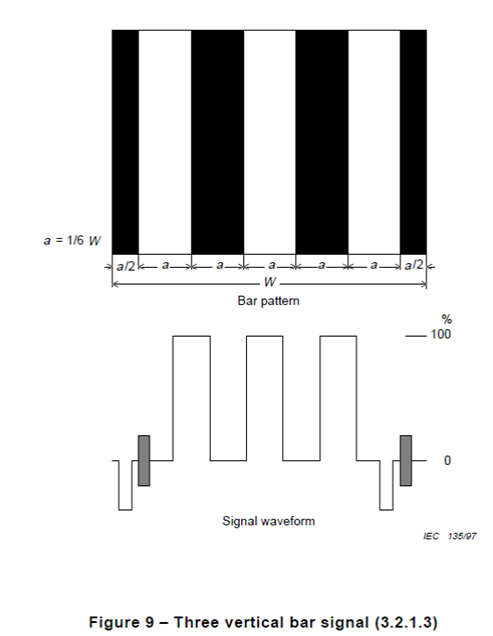
Three vertical bar signal’ shall be used as defined in 3.2.1.3 of IEC 60107-1:1997
3.2.1 .3 Three vertical bar signalE.L. IEC 60238 A1 2017 2018-04-03.doc
The three vertical bar signal produces three equidistant vertical white bars on a black background. The width of each bar is 1 /6 times the nominal horizontal width ( W ) of the picture.
A line-time waveform of the signal is shown in figure 9. This signal has an APL of 50 % and includes the reference white level. It is suitable for setting the output signal level and the luminance level of white For the SECAM measurements, the subcarrier with the frequency and amplitude corresponding to black and white is superimposed on the signal.
The same bar width can be applied for the wide aspect ratio picture.
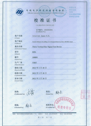
RDL-100 video signal generator Calibration report....
IEC Test Equipment
IEC Test Equipment
IEC Test Equipment
